80
Operating Instructions – Electronic Motor DRC.-..-SNI
6
Starting up the GIO13B application option
Startup
6.6.2 Setting the DIP switches
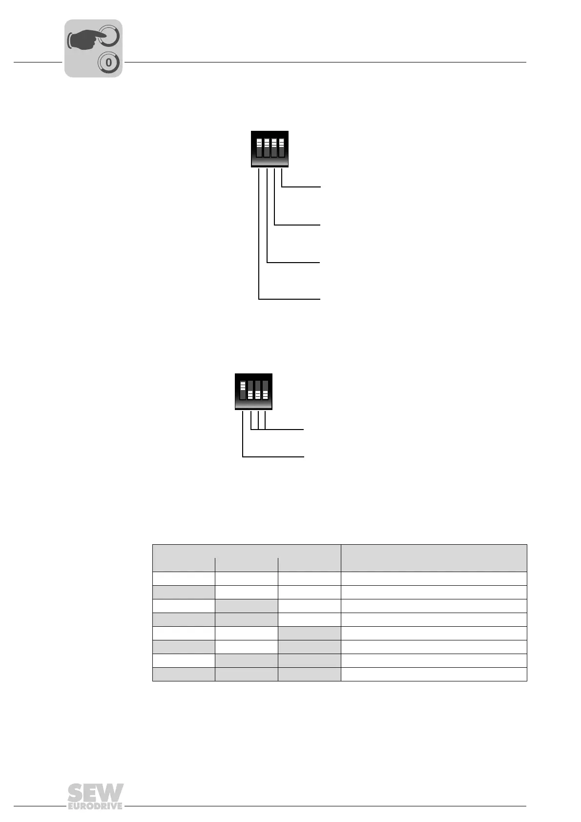
DIP switch S1 The following figure shows the possible settings for DIP switch S1:
DIP switch S2 The following figure shows the possible settings for DIP switch S2:
The DIP switches S2/1 to S2/3 are used to configure the primary frequency input. The
following table shows the corresponding configuration options:
9007201137841035
ON DIP
1234
S1
S1/4: Binary output
ON = Binary output ON
OFF = Binary output OFF
S1/3: Analog output
ON = Analog output ON
OFF = Analog output OFF
S1/2: Binary inputs
ON = Binary inputs ON
OFF = Binary output OFF
S1/1: Analog input
ON = Analog input ON
OFF = Analog input OFF
9007201137842955
DIP switch Configuration
S2/2 S2/3 S2/4 Primary frequency input, maximum frequency
OFF OFF OFF f = 1 kHz
ON OFF OFF f = 2 kHz
OFF
ON OFF f = 5 kHz
ON ON OFF f = 10 kHz
OFF OFF
ON f = 20 kHz
ON OFF ON f = 40 kHz
OFF
ON ON f = 80 kHz
ON ON ON f = 120 kHz
ON DIP
1234
S2
S2/2 to S2/4:
Configuration of primary frequency input
S2/1: Primary frequency input
ON = Primary frequency input ON
OFF = Primary frequency input OFF