Chapter 6 Operating Instructions
CLV65x Bar Code Scanner
62 © SICK AG · Division Auto Ident · Germany · All rights reserved 8011980/0000/2009-04-21
Electrical installation
6.4.5 Wiring switching inputs
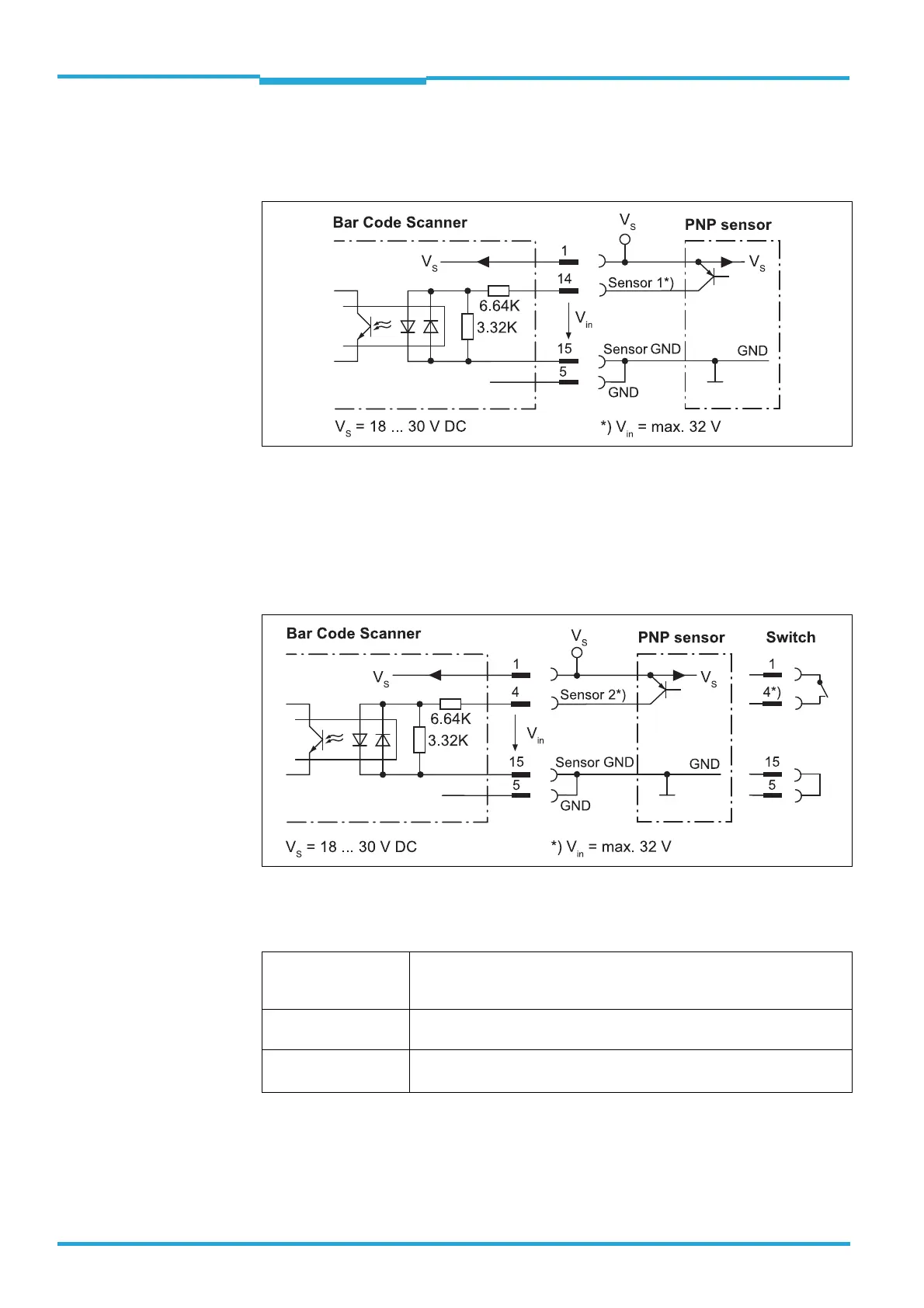
If the bar code scanner's reading process should be triggered by an external sensor, the rea-
ding pulse sensor is connected to the "Sensor 1" switching input.
Fig. 6-6: Wiring the “Sensor 1“ switching input on the 15-pole D-Sub-HD plug
The "Sensor 2" switching input has the following functions, among others:
Trigger source for
• Incremental encoder input
• Reading pulse generator for reading pulse end
Fig. 6-7: Wiring the “Sensor 2“ switching input on the 15-pole D-Sub-HD plug
Important The ratings for "Sensor 1" and "Sensor 2" are identical.
Tab. 6-7: Ratings for the switching inputs
Connect switching inputs depending on application.
Switching behaviour Power fed to the input opens the internal reading gate of the bar code
scanner.
(Default setting: active high; debouncing: max. 30 ms (standard))
Features – Optodecoupled, reverse polarity protected
– Can be wired with the PNP output of a sensor
Electrical values Low: |V
in
| ≤ 2 V; |I
in
| ≤ 0.3 mA
High: 6 V ≤ |V
in
| ≤ 32 V; 0.7 mA ≤ |I
in
| ≤ 5.0 mA

 Loading...


