Operating Instructions Chapter 6
CLV65x Bar Code Scanner
Electrical installation
8011980/0000/2009-04-21 © SICK AG · Division Auto Ident · Germany · All rights reserved 65
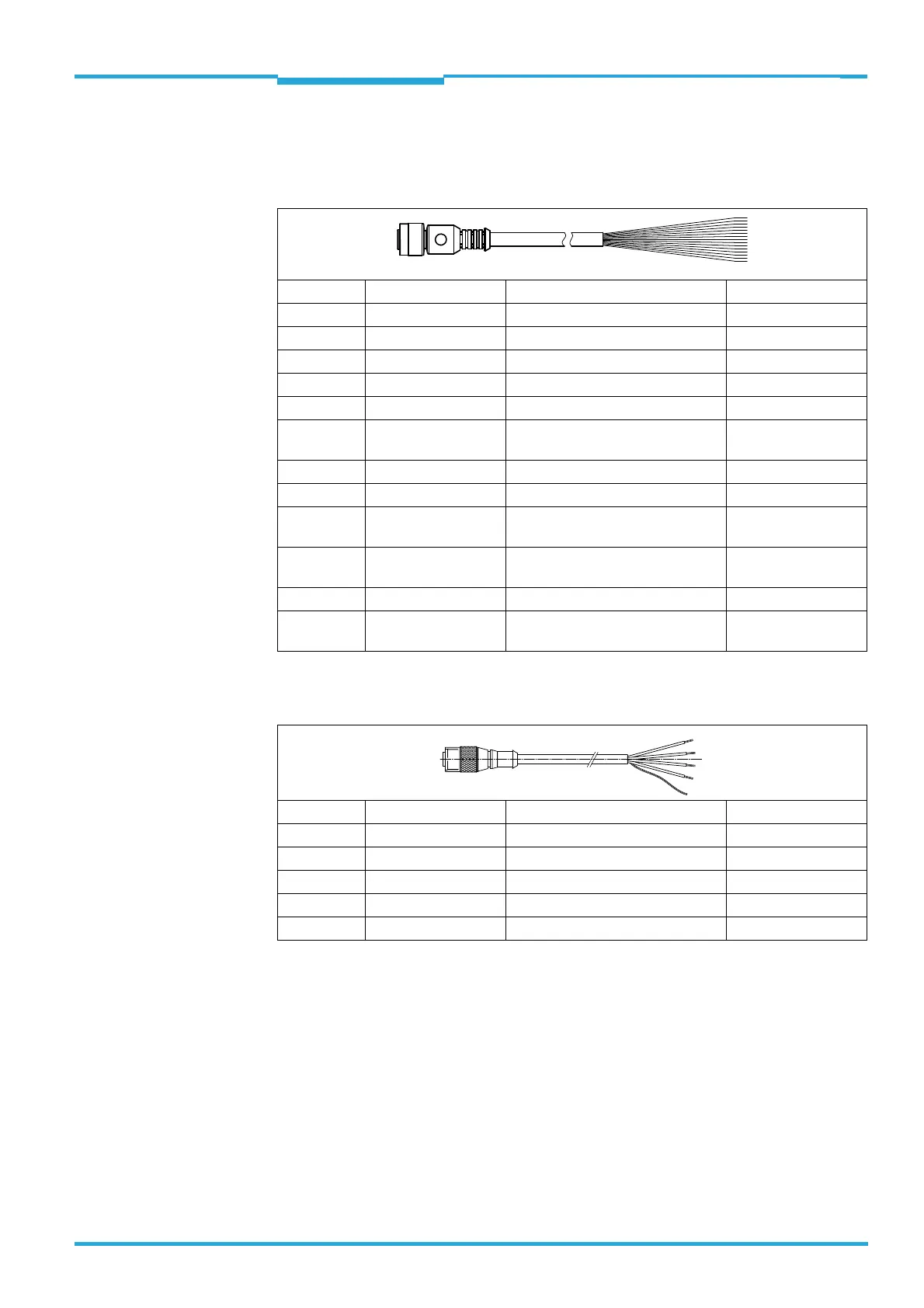
6.5.2 Pin assignment and wire colour assignment of the assembled cables with an
open end
Cable no. 6034605 (Ethernet version)
Tab. 6-11: Pin assignment of the 12-pole M12 socket and wire colours at the open end
Cable no. 6012166
Tab. 6-12: Pin assignment of the 5-pole M12 plug and wire colours at the open end
Pin (12-pole) Signal Function Wire colour
1 GND Ground brown
2 18 ... 30 V DC Supply voltage blue
3 CAN L CAN bus (IN/OUT) white
4 CAN H CAN bus (IN/OUT) green
5 TD+ (RS-422/485) Host interface (sender) pink
6 TD– (RS-422/485);
TxD (RS-232)
Host interface (sender) Yellow
7 TxD (Aux) Aux interface (sender) black
8 RxD (Aux) Aux interface (receiver) grey
9 SensGND Common ground for the switching
inputs
Red
10 Sensor 1 Digital switching input for external
reading pulse
violet
11 RD+ (RS-422/485) Host interface (receiver) grey-pink
12 RD– (RS-422/485);
RxD (RS-232)
Host interface (receiver) red-blue
Pin (5-pole) Signal Function Wire colour
1– Shield –
2 +24 V DC Supply voltage Red
3GND Ground black
4 CAN H CAN bus (IN/OUT) white
5 CAN L CAN bus (IN/OUT) blue

 Loading...


