Chapter 4 Operating Instructions
CLV65x Bar Code Scanner
26 © SICK AG · Division Auto Ident · Germany · All rights reserved 8011980/0000/2009-04-21
Product description
4.3 Device versions
The CLV65x bar code scanner with a glass reading window is available in the following ver-
sions, among others:
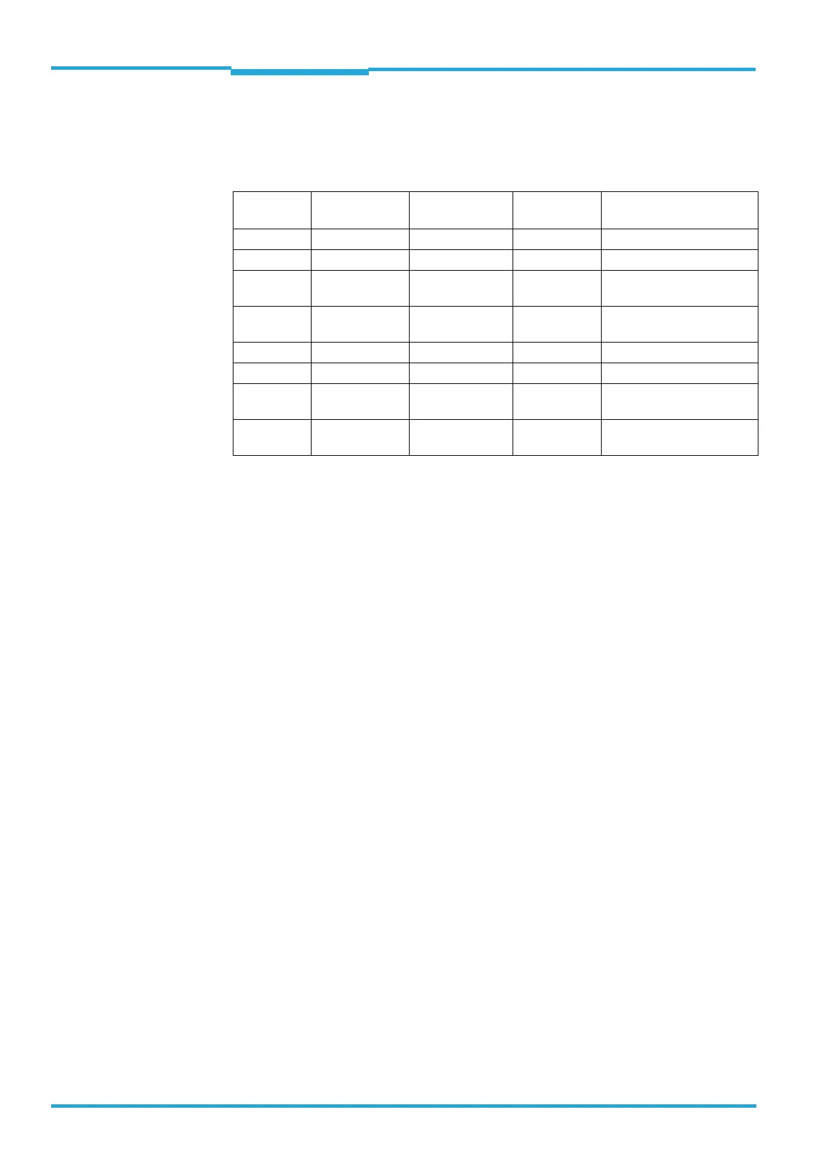
Tab. 4-2: Variants of the CLV65x Bar Code Scanner
Important Depending on the connection (design), the following interfaces are available:
• Standard version (cable with connector)
– RS-232, RS-422/485, CAN, two digital switching inputs, two digital switching out-
puts, power supply
• Ethernet version (revolving connector unit)
– Connector 1: Ethernet
– Connector 2: RS-232, RS-422/485, CAN, one digital switching input, power supply
4.4 System requirements
General system requirements derive from the bar code scanner's technical data (see
chapter 10 Technical data, page 81).
The requirements and conditions for Installation, Electrical installation and Startup and
configuration are summarised in the respective chapters.
Order no. Type Scanning method Reading
window
Connection (design)
1041290 CLV650-0000 Line scanner On front Cable with connector
1042121 CLV650-0120 Line scanner On front Connector unit on device
1042124 CLV650-6000 Line scanner with
oscillating mirror
On side Cable with connector
1042125 CLV650-6120 Line scanner with
oscillating mirror
On side Connector unit on device
1046557 CLV651-0000 Line scanner On front Cable with connector
1046558 CLV651-0120 Line scanner On front Connector unit on device
1046559 CLV651-6000 Line scanner with
oscillating mirror
On side Cable with connector
1046560 CLV651-6120 Line scanner with
oscillating mirror
On side Connector unit on device

 Loading...


