Operating Instructions Chapter 6
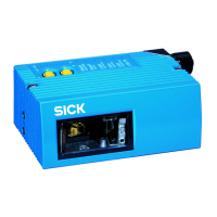
CLV65x Bar Code Scanner
Electrical installation
8011980/0000/2009-04-21 © SICK AG · Division Auto Ident · Germany · All rights reserved 53
6 Electrical installation
6.1 Overview of installation sequence
Important Electrical installation must be performed by qualified staff.
The following list provides an overview of a typical installation sequence:
• Connect bar code scanner to connection module CDB620 or CDM420
• Wire the bar code scanner's data and function interfaces
• Connect connection module to the supply voltage
• Connect PC for start-up and configuration (RS-232 or Ethernet)
The actual installation work which has to be carried out depends on the respective system
configuration and the version of the bar code scanner (see the following chapter). Once
electrical installation has been completed, the bar code scanner is started up and confi-
gured (see chapter 7 Startup and configuration, page 67).
6.2 Electrical installation preparations
The following general requirements should be observed for the electrical installation:
• Supply voltage 18 ... 30 V DC (functional extra-low voltage in accordance with IEC
60364-4-41 (VDE 0100 Part 410)) and min. 10 W output power
– Using connection module CDB620/CDM420: supply voltage provided by terminals
of the connection module
- or -
Free wiring by customer (without connection module CDB620/CDM420): connec-
tion of supply voltage e.g. by cable no. 6034418 (15-pole D-Sub-HD socket to open
end)
• With external reading pulsing
– Appropriate reading pulse sensor (start/stop), e. g. photoelectric reflex switch:
for registering an object in the reading area
– Additional appropriate reading pulse sensor (stop), e.g. photoelectric reflex switch:
For registering the end of pulse with extended external reading pulse
• Appropriate incremental encoder: For separating identical bar codes
• Host computer with RS-232, RS-422/485 data interface or Ethernet: For further pro-
cessing the reading data
• Connection cables: see ordering information for " Bar Code Scanner CLV600" product
information.
Important The possible distance between the bar code scanner and the host computer depends on
the physical version of the selected host interface and the set data transfer rate.
The following resources are required for electrical installation:
•Tool
• Digital measuring device (current/voltage measurement)

 Loading...