Chapter 6 Operating Instructions
CLV65x Bar Code Scanner
56 © SICK AG · Division Auto Ident · Germany · All rights reserved 8011980/0000/2009-04-21
Electrical installation
6.3.2 Bar code scanner connections to the cable and connector (standard version)
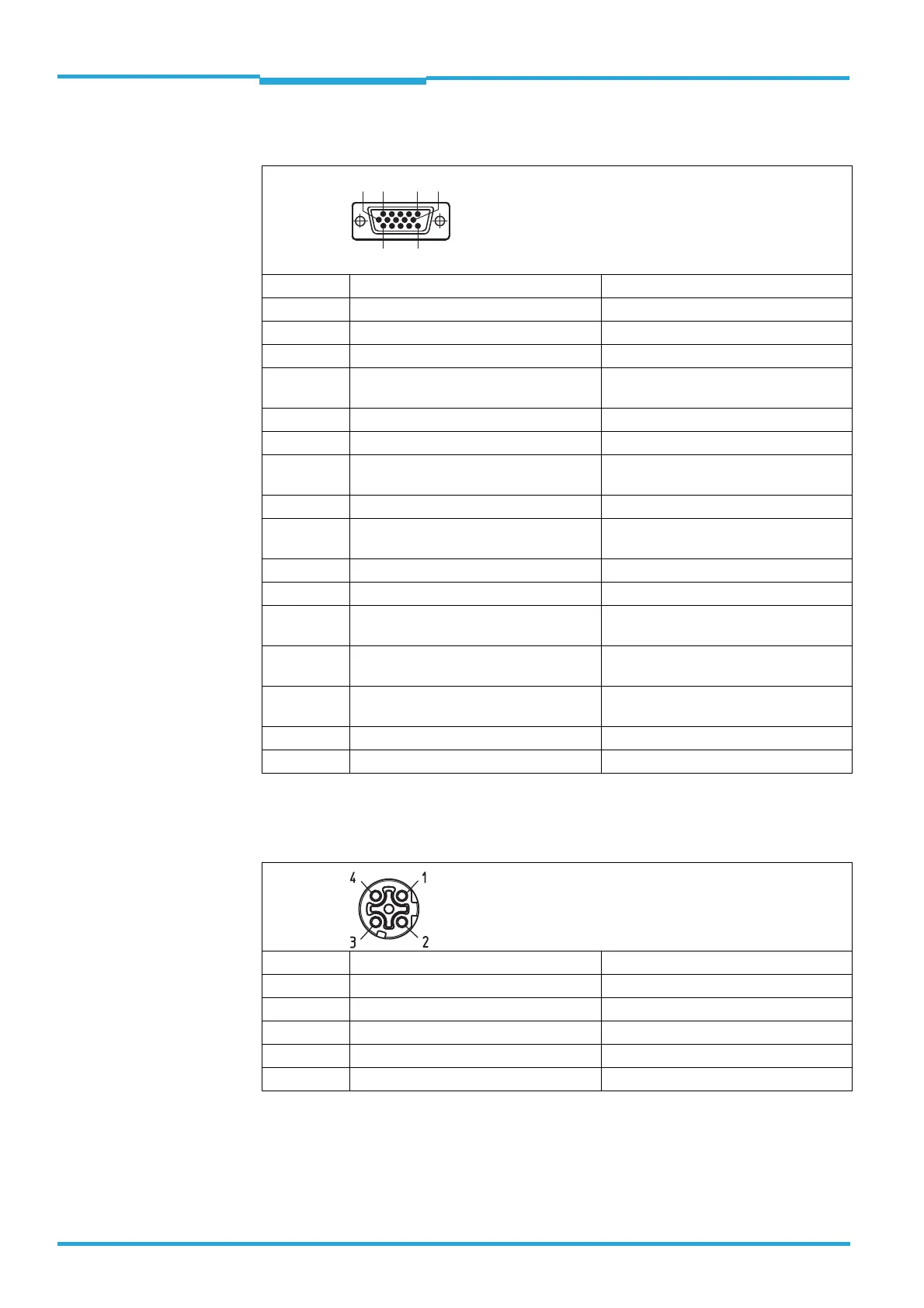
Tab. 6-3: Standard version: Pin assignment of the 15-pole D-Sub-HD cable connector
6.3.3 Bar code scanner's connections with connector unit (Ethernet version)
Tab. 6-4: Ethernet version: Pin assignment of the 4-pole M12 socket
Pin Signal Function
1 18 ... 30 V DC Supply voltage
2 RxD (Aux) Aux interface (receiver)
3 TxD (Aux) Aux interface (sender)
4 Sensor 2 Digital switching input (adjustable func-
tion, e. g. external reading pulse)
5GND Ground
6 RD+ (RS-422/485) Host interface (receiver)
7 RD– (RS-422/485);
RxD (RS-232)
Host interface (receiver)
8 TD+ (RS-422/485) Host interface (sender)
9 TD– (RS-422/485);
TxD (RS-232)
Host interface (sender)
10 CAN H CAN bus (IN/OUT)
11 CAN L CAN bus (IN/OUT)
12 Result 1 Digital switching output, adjustable func-
tion
13 Result 2 Digital switching output, adjustable func-
tion
14 Sensor 1 Digital switching input for external rea-
ding pulse
15 SensGND Common ground for the switching inputs
–– Shield
Pin Signal Function
1TD+ Transmitter+
2RD+ Receiver+
3TD– Transmitter-
4RD– Receiver-
–– Shield
56
11
10
15
1

 Loading...


