Operating instructions Chapter 12
S100
8012238/YY30/2015-02-20 © SICK AG • Subject to change without notice 57
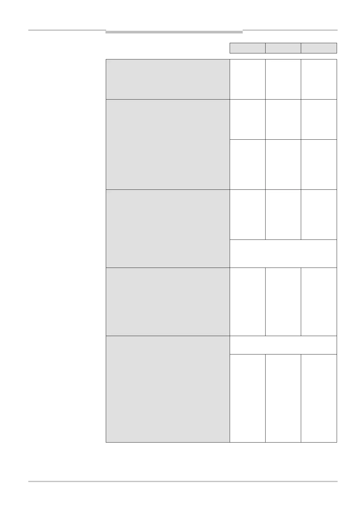
Minimum Typical Maximum
Cable length for power supply tolerance ±5%
For wire cross-section 1 mm² 60 m
For wire cross-section 0.5 mm² 30 m
For wire cross-section 0.25 mm² 15 m
Cable length for power supply tolerance ±1%
For wire cross-section 1 mm² 70 m
For wire cross-section 0.5 mm² 35 m
For wire cross-section 0.25 mm² 17 m
Stand-by mode input
Input resistance when HIGH 2 k
Voltage for HIGH 11 V 24 V 30 V
Voltage for LOW –3 V 0 V 5 V
Static input current 6 mA 15 mA
Static control inputs
Input resistance when HIGH 2 k
Voltage for HIGH 11 V 24 V 30 V
Voltage for LOW –3 V 0 V 5 V
Static input current 6 mA 15 mA
Input frequency
(max. switching sequence or frequency)
1/t
UFVz
+ 40 ms
(t
UFVz
= time set for advancing the
timing for the switching)
Application diagnostic output
error/contamination
HIGH switching voltage at 200 mA U
V
– 3.3 V U
V
Source switching current 100 mA 200 mA
Current limiting (after 5 ms at 25° C) 600 mA 920 mA
Power up delay 1.4 ms 2 ms
Switch off delay 0.7 ms 2 ms
Switching outputs Q1 and Q2 PNP semiconductors, short-circuit
protected
11)
HIGH switching voltage at 250 or 150 mA U
V
– 2.7 V U
V
Switching voltage LOW 0 V 0 V 3.5 V
Source switching current
6 mA 0.25 A
Leakage current 250
A
Load inductance 2.2 H
Load capacity 2.2
F at
50
Switching sequence (without switching) 5
/
s
Permissible cable resistance 2.5
11)
Applies to the voltage range between V
s
and 0 V.
12)
Switching currents up to 500 mA are allowed briefly (≤100 ms).
 Loading...