25
8014084/ZWT7/V3-1/2020-06 | SICK OPERATING INSTRUCTIONS | TRANSIC111LP
Subject to change without notice
INSTALLATION 3
3.3.4 TRANSIC111LP installation – ambient gas measurements
Installation Instructions
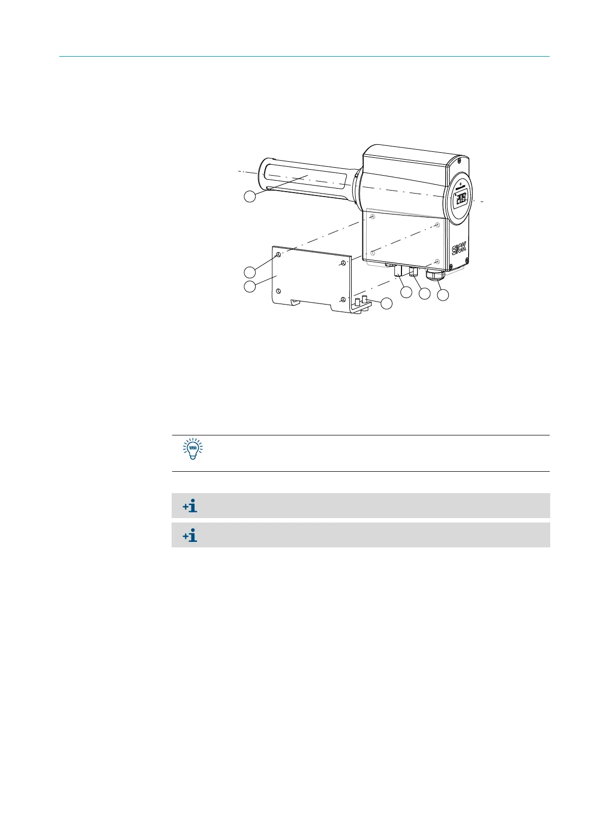
Fig. 10: TRANSIC111LP, fitted on a wall
1
Fit the wall bracket to the 4 drill holes.
2 Fasten the TRANSIC111LP to the wall with the four M6 screws.
3 Tighten the four screws.
1 = Stainless steel filter
2 = External grounding connection
3 = Calibration gas inlet with a Ø 6 mm Swagelok connection (optional)
4 = M20 × 1.5 cable gland for supply and signal lines
5 = Max. screw size M6
6 = Wall bracket
7=Device screws
First fix both outer screws in the threads at the bottom of the TRANSIC111LP. This
simplifies fastening the two inner screws when positioning the TRANSIC111LP on the
wall bracket.
Dimensions and drill holes for the wall bracket, see “Wall bracket”, page 96.
Ensure the TRANSIC111LP is installed in a representative gas mixture.