91
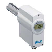
8014084/ZWT7/V3-1/2020-06 | SICK OPERATING INSTRUCTIONS | TRANSIC111LP
Subject to change without notice
TROUBLESHOOTING 8
8 Troubleshooting
8.1 Function errors
The TRANSIC111LP monitors its operation. Monitoring includes:
1 Self-test
2 Error detection during operation
3 Error output
8.1.1 Self-test
A self-test is always carried out when the TRANSIC111LP is switched on.
External conditions can cause the self-test to fail, for example, when the lens or mirror are
steamed up due to strong condensation in the probe. The signal level is insufficient. The
TRANSIC111LP is reset after 10 minutes when the self-test fails due to external factors.
8.1.2 Error control and error categories
There are 3 error categories:
● Fatal errors: Lead to a permanent error state.
● Nonfatal errors: Deactivated automatically when certain conditions are fulfilled. These
errors can also be deactivated manually.
● Warnings: Measurement continues but a maintenance request is reported. Warnings
can be deactivated manually.
All errors are always cleared during a start.
All error events are stored in an EEPROM error memory.
8.1.3 TRANSIC111LP behavior when errors occur
Emergency shutdown state
If a processor or memory error occurs, the TRANSIC111LP switches to the emergency
shutdown state and cannot be started:
TRANSIC111LP Fatal error Non-fatal error Warnings
Analog output Programmable, Fail High or
Fail Low
Programmable, Fail High or
Fail Low Standard = 3 mA
Normal operation
LED Red LED blinks rapidly Red LED blinks slowly Yellow LED blinks
Digital output Open Open Closed;
optional: Open when the digi-
tal output is used for signal-
ing warnings.
Display Error codes are displayed Error codes are displayed Measured value is displayed
Maintenance inter-
face
STOP mode: Sends error
message
RUN mode: O2 value =
***.**
POLL mode: O2 value =
***.**
STOP mode: Sends error
message
RUN mode: O2 value =
***.**
POLL mode: O2 value =
***.**
STOP mode: Sends error
message
RUN mode: Normal operation
POLL mode: Normal opera-
tion
Error counter Error counter(s) incremented Error counter(s) incremented Error counter(s) incremented
Error log Error is written to log Error is written to log Error is written to log
Table 12: Device status for error and warnings
Analog output 0.0 mA
LED Red LED on
Digital output Open