68
8014084/ZWT7/V3-1/2020-06 | SICKOPERATING INSTRUCTIONS | TRANSIC111LP
Subject to change without notice
6 ADJUSTMENT
6.1.2.3 Adjusting gas flow
1 Open the gas cylinder valve with care to avoid pressure surges.
2 Completely open the flowmeter.
3 Slowly increase the pressure setting of the controller until the gas flow can be detected
with the rotameter
4 Use the flowmeter to adjust the volume flow to the desired value.
5 Pay attention to the volume flow for optimum adjustment precision.
For further information on adjustment precision and volume flow, see “Calibration and
adjustment in the process”, page 67.
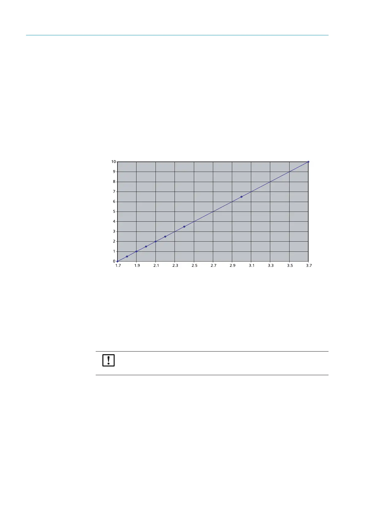
6 Observe Fig. Fig. 34 for adjustment without flowmeter. Information on the relation
between span gas volume flow and span gas pressure of the optional test gas inlet can
be found there.
0511-052
Fig. 34: Volume flow against pressure, Swagelok SS-CHSM2-KZ-25 non-return valve
6.1.3 Information on calibration gases
● Factory calibration: Mixtures of dry N
2
and O
2
.
● Humidity / CO
2
concentration of calibration gases: 0%.
● Gases recommend for adjustment: Nitrogen gas mixtures
● A gas flow rate of about 5 l/min is adequate for TRANSIC111LP calibration and adjust-
ment. Shorter response times during calibration and adjustment require a higher volume
flow. The higher the gas volume, the higher the gas pressure. Select an adequate tubing
size for the escaping gas.
Pressure (bar)
Volume flow (l/min)
NOTICE:
Allow enough time for the gas concentration to stabilize when doing calibrations/
adjustments.