22
8014084/ZWT7/V3-1/2020-06 | SICKOPERATING INSTRUCTIONS | TRANSIC111LP
Subject to change without notice
3 INSTALLATION
3.3.3 TRANSIC111LP installation - extractive
Filter recommendation
● Stainless steel filter: Minimum protection against dirt particles
● PTFE filter: For gas with humidity and/or fine dirt particles
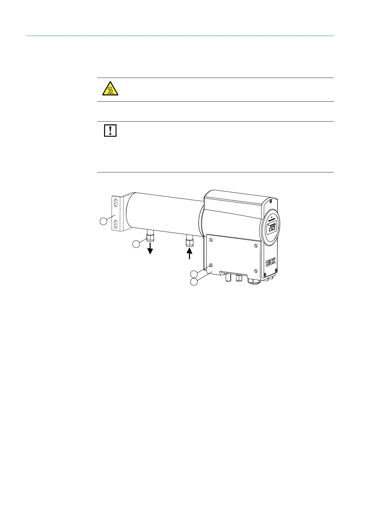
Fig. 7: TRANSIC111LP with sample gas cell
Installing the wall bracket
1 Fasten the wall bracket.
Wall bracket dimensions, see “ TRANSIC111LP with wall bracket and sample gas cell”,
page 99.
2 Fasten the TRANSIC111LP
1 Install the TRANSIC111LP on the wall bracket using the four M6 screws provided.
2 First fix both outer screws in the threads at the bottom of the TRANSIC111LP. This
simplifies fastening the two inner screws when positioning the TRANSIC111LP on the
wall bracket.
3 Tighten all four screws.
CAUTION: Risk of burns through hot gas
▸ Attach the enclosed warning label to the sample gas cell surface when process
temperatures are >65 °C.
NOTICE: Preparing the gas sample for dirty and wet gas
▸ Filter and dry the gas sample before pumping it into the sample gas cell.
▸ Use a hydrophobic dust filter before the inlet opening of the sample gas cell to
protect the optical components against particle and water.
▸ Replace the dust filter regularly to ensure sufficient throughflow.
▸ Dry the gas through cooling and reheating to guard against condensation in the
sample gas cell.
1 = Optionally available assembly bracket
2 = Swagelok connections for Ø 6 mm gas tubes (in scope of delivery: Adapter for 1⁄4")
3 = Max. screw size M6
4= Wall bracket