29
8014084/ZWT7/V3-1/2020-06 | SICK OPERATING INSTRUCTIONS | TRANSIC111LP
Subject to change without notice
INSTALLATION 3
3.4.2 Connecting the 24V PELV power supply unit
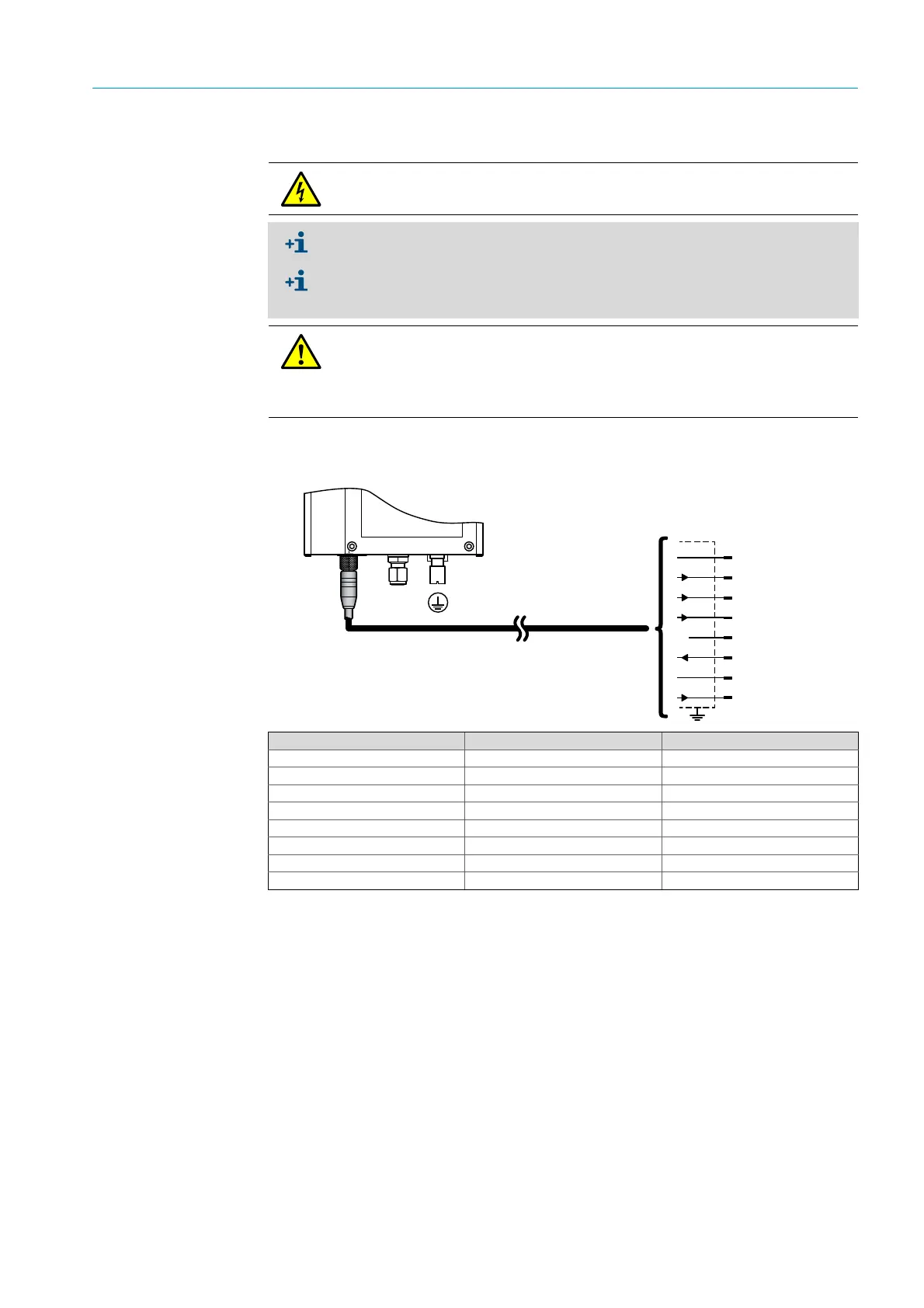
3.4.3 Connecting the TRANSIC111LP via an 8-pole plug connector
Fig. 13: Optional 8-pole plug connector
CAUTION: Electrical voltages
▸ Always ensure the lines are disconnected before carrying out any electrical work.
The 24V PELV power supply unit must have an overvoltage protection device.
A disconnecting device must be provided to disconnect the device from the power
supply. Fit the disconnecting device as close as possible to the measuring device and
easily accessible.
WARNING: Caution: Risk of fire caused by excessive energy input in error case
A PELV power supply unit (11 ... 36 V DC, 24 V DC recommended) is required.
The installer/operating company is responsible for correct selection.
The installer of a system is responsible for the safety of a system in which the device is
integrated.
RS-485, A
AO: – (0/4 mA)
DO
AO: + (20 mA)
M
L+ (24 V DC)
RS-485, B
DO
wht
brn
grn
yel
gre
pnk
blu
red
5
6
7
8
1
2
4
3
Terminal Color Connection No.
24 V pink 6
0 V grey 5
Iout+ yellow 4
Iout− brown 2
RS-485 A white 1
RS-485 B blue 7
Alarm red 8
Alarm green 3
Table 1: Connections of 8-pole plug connector