28
8014084/ZWT7/V3-1/2020-06 | SICKOPERATING INSTRUCTIONS | TRANSIC111LP
Subject to change without notice
3 INSTALLATION
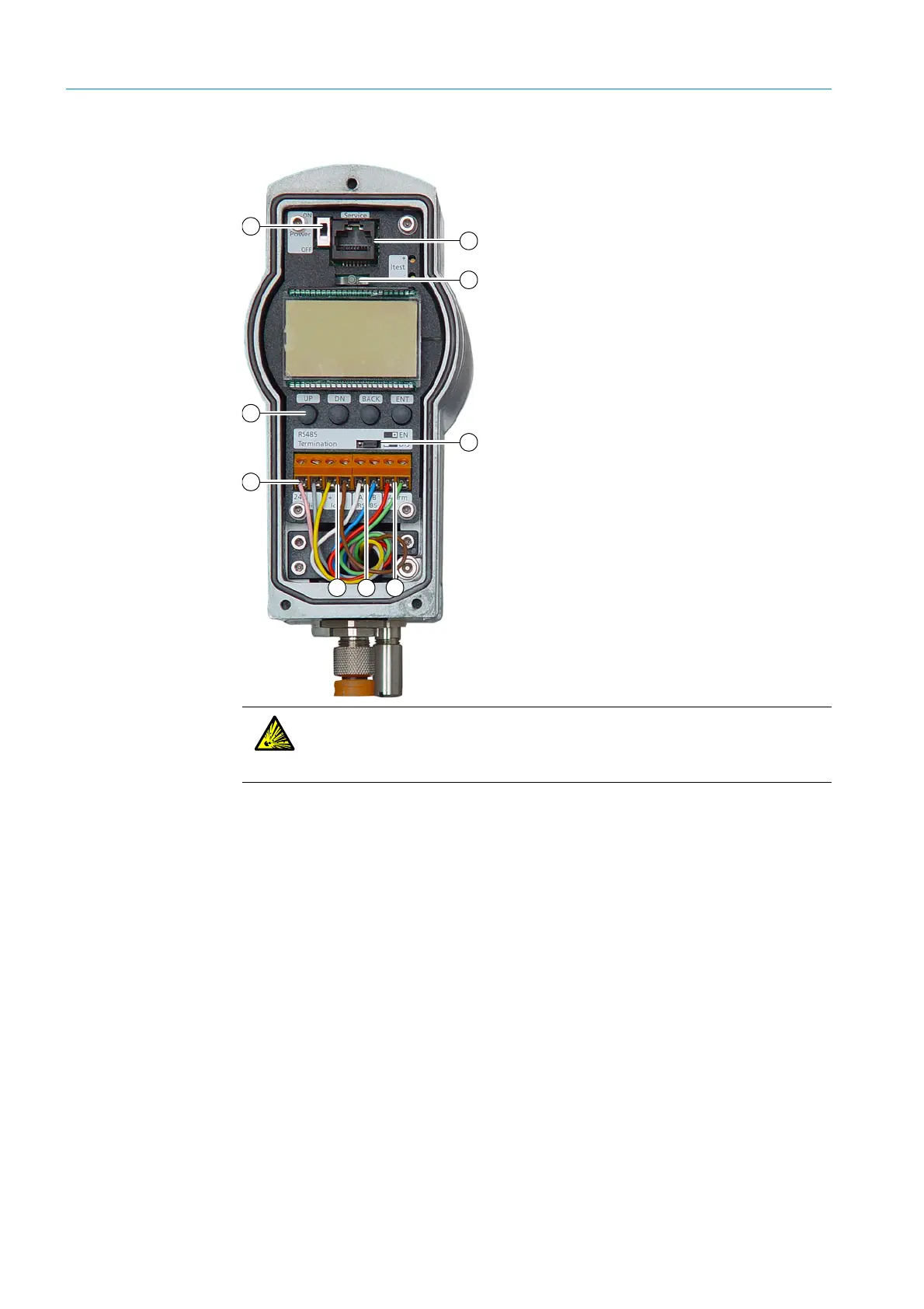
Fig. 12: Connections at the integrated interface
1 Remove the cover.
2 Set the ON/OFF switch to OFF.
3 Push the cable through the cable gland.
4 Connect power supply terminals (24 V) and (0).
5 Connect current output: The current output is between terminals Iout (+) and (−). The output can
be checked with an amperemeter.
6 A two-wire RS-485 line is available between terminals RS 485 (A) and (B).
Line termination can be enabled by changing the RS-485 termination jumper position to EN.
7 A potential-free relay contact is available between the two Alarm terminals. For further information,
see Page 53.
8 Close the cable gland. Tightening torque: 10 Nm
9 Ensure the cable gland seals the cable.
10 Switch the transmitter on using the Power ON/OFF switch.
11 The TRANSIC111LP performs a self-test. PASS is displayed after termination of the self-test.
Shortly after the self-test, the device is ready for measurement and starts displaying measured
oxygen values. A green LED lights when the transmitter has found the absorption line and can
output valid measured values.
12 Close the device front panel.
13 Ensure the enclosure is closed tight.
14 The transmitter is now ready for use.
1 Maintenance interface (RS-232)
2LED lamp
3 ON/OFF switch
4Keypad
5 Voltage supply
6 Analog output
7 Bus interface RS485
8 Digital output
9 Line termination RS-485
3
5
6 8
1
7
2
9
4
WARNING: Risk of explosion when activating the ON/OFF switch
Do not activate the switch in potentially explosive atmospheres due to the risk of
sparking.
▸ Always set the ON/OFF switch to ON outside the potentially explosive atmosphere.