65
8014084/ZWT7/V3-1/2020-06 | SICK OPERATING INSTRUCTIONS | TRANSIC111LP
Subject to change without notice
ADJUSTMENT 6
6Adjustment
Definition of calibration and adjustment for these Operating Instructions
● Calibration: The comparison between the measured value of the device and a reference
concentration
● Adjustment: Change the device measured value so that it corresponds to the reference
concentration.
6.1 Hardware preparations
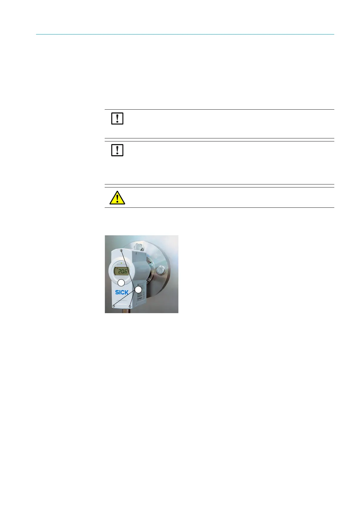
Fig. 32: TRANSIC111LP in the process
Getting started
1 Switch the TRANSIC111LP on at least 15 minutes before calibration or adjustment.
2 Calibration: Simply observe the measured values displayed by the measuring device.
3 The serial interface as well as the keypad on the front of the device can be used for
adjustment:
▸ Open the front cover of the measuring device with a 4 mm hex socket (Allen) key.
– Serial interface :
▸ Connect the TRANSIC111LP with the computer via the serial interface cable.
▸ Open the Terminal program with the respective serial communication setting
(standard setting: 19200/8/N/1).
▸ Connect the gas supply,see “Setting up the gas supply for calibration and adjust-
ment”, page 66, and calibrate/adjust, see “Calibration”, page 79, and/or see “Infor-
mation on adjustment”, page 80.
Read the instructions through carefully before making any settings or parameter
changes. SICK accepts no responsibility for parameter or setting changes nor adjust-
ments made by the user. Contact SICK Customer Service when you require technical
support or help.
CAUTION: Differences between calibration and adjustment of the different
TRANSIC111LP variants
Calibration and adjustment of the variants for installation in processes and with sample
gas cells differ slightly from calibration and adjustment of the ambient gas measure-
ment version. Make sure you read the correct Section. Section 8 covers calibration and
adjustment of the ambient gas measurement version.
WARNING: Observe all safety instructions, see “Safety information”, page 18.
1
2
1= Front of the device
2= Allen screws