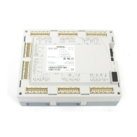
LMVSeriesTechnicalInstructions
DocumentNo.LV5‐1000
SCCInc. Page5 Section4
6. LMV52/VFDcombinationmustbe“Standardized”beforeoperation.SeeSection5(VSD)for
moredetails.
a. Verifythattheairdamperopenstopre‐purgepositionbeforetheblowerisenergized
forstandardization.
Pre‐RequisitesforLMV52SystemswithO2Trim
1. AllprerequisitesoftheBasicLMV51systemapply.
2. TheO
2
sensormustbemountedcorrectly. SeeAppendixB(LMV5AccessoriesGuide)formore
details.Particularattentionshouldbepaidtothefollowing:
a. IftheO
2
sensorcannotbeinstalledperAppendixB(LMV5AccessoriesGuide),contact
SCCforassistance.
b. TheQGO20O
2
sensorisnotsuitedformosttypesofbiogasorfuelsthatproduceash,
suchas#6oil.ContactSCCforadviceonthecompatibilityofuncommonfuels.
3. TheO
2
sensormustbewiredtothePLL52correctly.SeeSection2(Wiring)formoredetails.
Particularattentionshouldbepaidtothefollowing:
a. ThePLL52modulemustbewithin30feetoftheO
2
sensor.
b. TwoconduitsmustberunbetweentheQGO20O
2
sensorandthePLL52module.One
conduitmustcontainthelowvoltagesignalswhiletheotherconduitmustcontainthe
highvoltageforthesensorheater.
4. Thefurnacepressureoftheboilerbeingcommissionedmustberepeatable atagivenfiringrate.
Repeatabilityof+/‐0.2inWCateachfiringrateisadequate.
5. Afuelflowmeterorsomemeansofdeterminingtheload(firingrate)to+/‐3%isrequired.A
moreaccurateloadnumb
er(+/‐3%)foreachcurvepointisnecessaryforreliableO
2
trim
functionality.
6. TheLMV52mustbepoweredandconfiguredfortheQGO20O
2
sensorfortwohourspriorto
commissioning.ThisisdonetolettheQGO20sensorheatupthoroughly.
7. Theboilermustbeuptonormaloperatingtemperature/pressureforatleastonehourbefore
commissioningtheO
2
trim.

 Loading...


