LMVSeriesTechnicalInstructions
DocumentNo.LV5‐1000
SCCInc. Page11 Section4
NOTE:Depending onthe directionof rotation,homepositionsetin theLMV5, andwhetherthe
actuator is activated or deactivated, the actuator may rotate as soon as itis addressed. For this
reason it is highly recommended that the actuator shaft be uncoupled from the valve / damper
untiltheparameterspertainingtotheaboveareset,andtheinitialLMV5ala
rmisreset.
5. Addresstheactuators.Thisisaccomplishedbythefollowingsteps:
a. Remove the outer black cover of all actuators to be addressed.This is done by
loosening the three Philips (Pozidriv) head screws on the cover and setting the cover
aside.
b. OntheAZL,themenupathwillbe:
Params&Display>Actuators>Addressing
Notethatwhenthe“Params& Display”menuisentered,itmaybenecessarytoenter
theOEMorserviceleve
lpassword.
c. Select the actuator to be addressed.When pro mpted, press the “Enter” key to begin
theaddressingassignment.
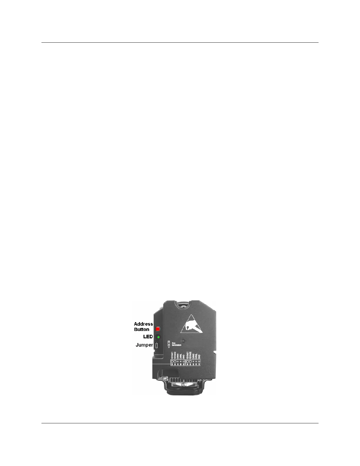
d. Press
the red button on the appropriate actuator.If done correctly, the AZL should
statethattheaddressassignmentwassuccessful.
e. Repeattheprocedureabovefortheotheractuators.
f. The jumper must be set to "Bus termination" on the last device on the CA
Nbus daisy
chain.ThelastdevicecouldbeanactuatororaPLLmodule.
g. Afterallact
uatorsaresuccessfullyaddressed,theouterblackcoverscanbereinstalled.
Figure4‐3:ActuatorwithCoverRemoved

 Loading...

