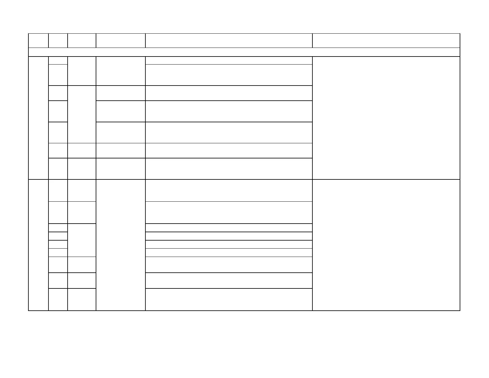
Device Display Meaning for the LMV5x System Corrective Action
Any # Running time fault of actuators or VSD.
01..3F
The diagnostic value is made up of the following faults or their
combinations (the individual diagnostic codes are added up in
01
Fault Running
Time Air Actuator
Running time fault of air actuator
04
Fault Running
Time Aux
Running time fault of auxiliary actuator 1
08
Fault Running
Time Aux
Running time fault of auxiliary actuator 2
10
VSD /
LMV5
Fault Running
Time VSD
Running time fault of VSD
20
LMV5
Fault Running
Time Aux
Running time fault of auxiliary actuator 3
Any #
VSD
Basic unit has detected that one or several actuators (incl. VSD
module) has / have not reached the special position pertaining
to the phase
01..3F
VSD
The diagnostic value is made up of the following faults or their
combinations (the individual diagnostic codes are added up in
hexadecimal format)
01 Positioning fault of air actuator
02 Positioning fault of active fuel actuator
04 Positioning fault of auxiliary actuator 1
08 Positioning fault of auxiliary actuator 2
10
VSD
Module
VSD has not reached the speed
20 Actuator Positioning fault of auxiliary actuator 3
40
VSD
Module
VSD quick shutdown, as the difference between the speed
setpoint and the actual speed exceeds the value permitted in
the TolQuick Shutdown parameter.
Fault with Positioning an Actuator or VSD Speed
Actuator /
VSD /
LMV5
Fault Running
Time
1D
1E
1) Check parameters TimeNoFlame and
OperatRampMod . These should be set to values
greater than the ramping time of the attached actuators
or VSD.
2) Check connected actuators to determine if their
torque rating is being exceeded (stuck damper or valve,
etc...).
3) Check the two 12V fuses located under black covers
on the right side of the LMV5.
4) Check the CANBus power supply (blue or black
transformer) terminal SEK2. Pin 1 and pin 4 should
have 12VAC to reference ground which is pin 2.
Voltage between pin 1 and pin 4 should be 24VAC.
Actuator
1) Check connected actuators to determine if their
torque rating is being exceeded (stuck damper or valve,
etc...).
2) Check the two 12V fuses located under black covers
on the right side of the LMV5
3) Check the CANBus power supply (blue or black
transformer) terminal SEK2. Pin 1 and pin 4 should
have 12VAC to reference ground which is pin 2.
Voltage between pin 1 and pin 4 should be 24VAC.
4) If a VSD is being used, check for filters, damping,
and / or delays on the input signal to the VSD. The
VSD should respond to the input signal in a linear
fashion. See Error Code 15 for more information.
Special Pos not
reached
Actuator /
LMV5
Section 7 Page 29 SCC Inc.

 Loading...

