Home
Siemens
Control Systems
LMV5 Series
Technical Instructions
Page 352
Siemens LMV5 Series - Page 352
374 pages
Manual
To Next Page
To Next Page
To Previous Page
To Previous Page
Loading...
Technical Instructions
LMV Series
Document No.
LV5-800
0
Appendix A
Page 22
SCC Inc.
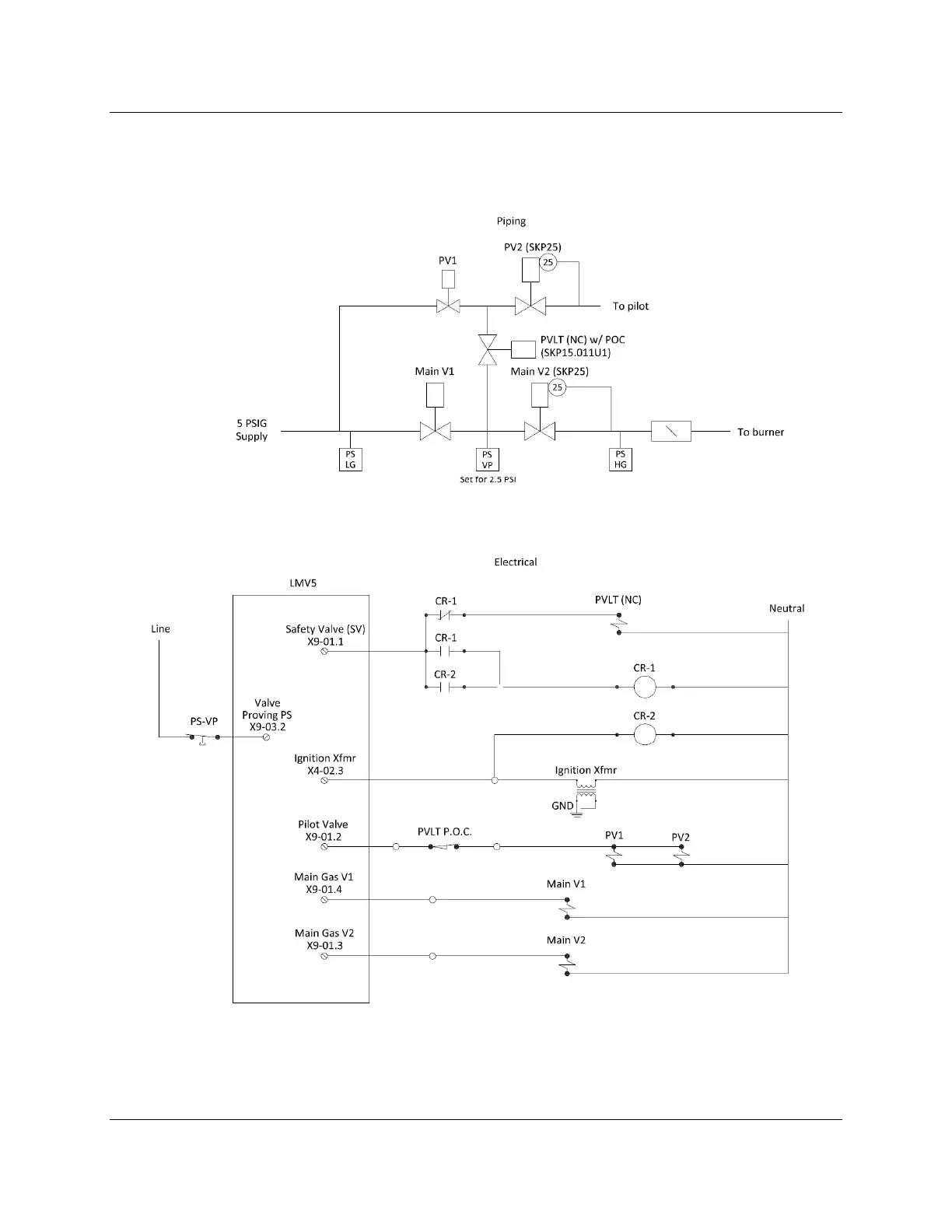
Pilot Valve Proving (continued)
Option 1:
On Startup with SKP25
’s on both
the Pilot and Main Gas Trai
ns
Figure 9: Opt
ion 1 Piping and Elect
rical Schematics
HOME
351
353
Table of Contents
Main Page
3-2: Parameter List
60
Default Chapter
60
Table of Contents
60
Lockouthistory
63
Gasfiring
64
Mint_Prepurgegas
65
Interval1Gas
66
Maxtmelowfire
67
Ignoilpumpstart
68
Mainsfrequency
69
Startreleasegas
70
Gaspressuremax
71
Heavyoildirstart
72
Standardfactor
73
Heavyoil
74
Homepos
75
Ignitionpos
76
Maxloadgas(Oil)
77
Loadmaskhighlim
78
Numfuelactuators
79
O2 Alarm
80
High-Fire
81
Loadctrlsuspend
82
O2Maxmanvariable
83
Load of Ignition
84
O2 Content Air
85
Manvar O2 Ctrl
86
Part
87
Minactuatorstep
88
Stageload
89
Maxtmemod
90
Mrange Presssens
92
Startadaption
93
Language
94
Addressing
95
Setteling Time
97
Max Stat Dev
98
Maxtempflgasgas
99
Thresholdfgr Gas(Oil)
100
Operationtempgas(Oil)
101
Gasfiring
102
OEM Password
103
Load_Sw_From_Pc
104
Section 4: Commissioning
119
120
Pre-Requisites for Basic LMV51 Systems
120
Pre-Requisites for LMV52 Systems with a VFD
122
Pre-Requisites for LMV52 Systems with O 2 Trim
123
Configuring (Parameterization Of) an LMV5 with a Default Parameter Set
124
Transferring Parameter Sets Using the AZL Display
132
Suggested Initial Light-Off for LMV5 Systems
133
Suggested Ratio Control Curve Commissioning
135
Suggested Load Control Setup
140
Suggested Cold Start (Thermal Shock Protection) Setup
142
Additional Tips for Commissioning
146
Special Features and Settings
148
Section 5 - Variable Speed Drive Control
153
154
Introduction
154
VFD and AC Induction Motor Fundamentals
154
Line Reactors
155
Output Wiring / Load Reactors
156
Shaft Current
157
Braking Resistors
157
Types of Vfds: Vector and Volt/Hz
159
Centrifugal Blower Fundamentals
159
Configuring Vfds for Use with the LMV52
160
Standardizing the LMV52
161
Blower Speed Monitoring
165
Suggested Setup Procedure for the VFD Control
167
Additional Tips for Burners with VFD Control
168
Section 6: Oxygen Trim
173
Introduction
174
O 2 Trim (O 2 Control) Fundamentals
174
174
Pre-Control
176
O 2 Trim Terminology
176
O 2 Control and O
178
Control and O Alarm Curves
178
O 2 Trim Configuration (Parameterization) before Commissioning
179
Suggested O 2 Trim Commissioning - Traditional Nozzle Mixing Burner with no or Low Percentage FGR (Typically LMV52.240)
181
Suggested O 2 Trim Commissioning - Premix Mesh Burner or Nozzle Mixing Burner with High Percentage of FGR (Typically LMV52.440)
186
Post Commissioning Tuning
192
Observing the Behavior of the O 2 Trim
196
Using the O Alarm Functionality Without O Trim
197
How the O 2 Is Measured with the QGO20 Sensor and PLL52 Module
198
Considerations When Using O Trim with FGR
201
7-1: Troubleshooting Introduction
209
Default Chapter
210
Canbus Faults Including "AZL Not on Bus" and "System Test
210
CanbusFaultsIncluding“AzlNotOnBus”And“SystemTest”
215
Fault Positioning Actuator - Error Code 15
215
Internal Fault Actuator - Error Code 19
215
Flame Failure - Error Code 25 or 26
216
Open Circuit / Short Circuit Sensor Faults - Error Code A6 (Diagnostics 50
217
Open Safety Loop - Error Code 21
218
LMV5 will Not Start (Stays in Phase 12)
219
LMV5 will Not Modulate Properly
220
221
O 2 Sensor Is Not Reading
221
O 2 Sensor Reading Grossly High or Low
222
O 2 Sensor Reads but Responds very Slowly
222
Ambient or Stack Temperature Sensor Reading Incorrectly
223
AZL Says "O2 Module Not Active or Not Available
223
AZL Says "O2 Setpoint Must Lie 0.1% below O2 Ratio Control" or "O2 Setpoint Must Lie 0.1% above O2 Min
224
AZL Says "Measurement Not Successful" When Measuring the Delay Time for O 2 Trim
225
AZL Says "O2 Trim Control Automatically Deactivated
226
227
VSD will Not Operate
227
Unsuccessful VSD Standardization
228
AZL Says "Fan Speed Not Reached" or "Control Range Limitation VSD Module
230
10-1: Introduction
309
Table of Contents
310
Section 10-2: LMV51 Software Version Updates
310
LMV51 Version 0210 to 0220
310
LMV51 Version 0230 to 0250
312
LMV51 Version 0250 to 0510
312
LMV51 Version 0510 to 0520
314
Load Controller Version 0140 to 0150
314
Load Controller Version 0150 to 0160
315
Load Controller Version 0160 to 0180
315
Load Controller Version 0180 to 0210
316
Section 10-3: LMV52 Software Version Updates
317
LMV52 Version 0130 to 0410
317
LMV52 Version 0410 to 0420
318
LMV52 Version 0420 to 0450
319
LMV52 Version 0450 to 0480
319
LMV52 Version 0480 to 0510
320
LMV52 Version 0510 to 1020
321
LMV52 Version 1020 to 1030
321
Load Controller Version Updates
321
VSD Module Version 0130 to 0140
322
VSD Module Version 0140 to 0150
322
Table of Contents
332
Direct Start
334
Introduction
334
Procedure
334
Operation
336
Hot Standby on a Steam Boiler with an RWF50 or RWF55
337
Introduction
337
Hot Standby with a Temperature Switch
342
Introduction
342
Procedure
343
Operation
343
Low Fire Hold with an RWF55
344
Introduction
344
Hot Water Boiler with an RWF55 with 3-Position Output
344
Hot Water Boiler with an RWF55 with Analog Output
344
Steam Boiler with an RWF55 with 3-Position Output
344
Steam Boiler with an RWF55 with Analog Output
344
Operation
349
Example
349
Pilot Valve Proving
350
Introduction
350
Procedure
350
Option 1: on Startup with Skp25'S on both the Pilot and Main Gas Trains
350
Important Notes
353
Sequence of Operation
353
Option 2: on Startup, SKP25 on the Main Gas Train, Solenoid Valves on the Pilot Train
354
Important Notes
355
Sequence of Operation
355
Option 3: Pilot Valve Proving on Startup and Main Valve Proving on Shutdown
356
Important Notes
357
Sequence of Operation
357
Purge Proving
358
Introduction
358
Procedure
358
Operation
359
Remote Setpoint
360
Introduction
360
Procedure
360
Example: Pressure Sensor Wired to Terminal X61
362
Example: Temperature Sensor Wired to Terminal X60
363
Example: Temperature Transmitter Wired to Terminal X61
364
Valve Proving with Two Pressure Switches
365
Introduction
365
Sequence of Operation
366
Important Notes
366
VFD Bypass
367
Introduction
367
Single Fuel Procedure
368
Single Fuel Operation
370
Dual Fuel Procedure
371
Dual Fuel Operation
372
Other manuals for Siemens LMV5 Series
Manual
39 pages
Basic Documentation
278 pages
Related product manuals
Siemens LMV51.140C1
327 pages
Siemens LMV52.240B1
327 pages
Siemens LMV52.440B1
327 pages
Siemens LMV 5 Series
16 pages
Siemens LGK16.322A27
28 pages
Siemens LGK16.635A27
28 pages
Siemens LOK16.250A27
28 pages
Siemens LGK16.335A27
28 pages
Siemens LGK16 Series
28 pages
Siemens LGK16.333A27
28 pages
Siemens LOGO! 12/24RCE
36 pages
Siemens LOGO! CSM 12/24
36 pages

 Loading...

