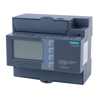
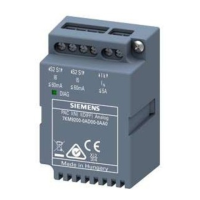
Connection
6.2 Connections
SENTRON PAC3200
Manual, 02/2008, A5E01168664B-04
79
No. Terminal Function
(4) IL2 l Phase current I
L2
, output
(5) IL3 k Phase current I
L3
, input
(6) IL3 l Phase current I
L3
, output
(7) V
1
Phase-to-neutral voltage V
L1
(8) V
2
Phase-to-neutral voltage V
L2
(9) V
3
Phase-to-neutral voltage V
L3
(10) V
N
Neutral conductor V
N
(11) L/+ AC: Connection: Conductor (phase-to-neutral
voltage)
DC: Connection: +
(12) N/- AC: Connection: Neutral conductor
DC: Connection: -
(13)
Reference potential
(14) DI- Digital input -
(15) DI+ Digital input +
(16) DO- Digital output -
(17) DO+ Digital output +
Grounding
Conductive panels and doors on control cabinets must be grounded. The doors of the control
cabinet must be connected to the control cabinet using a grounding cable.
Reference potential
Figure 6-5 Terminal block: digital input and output, reference potential
(13) Reference potential terminal
The connection "reference potential" discharges interference affecting the digital input
and output and the RJ45 connector.
Connect the reference potential to the equipotential bonding strip in the control cabinet.
 Loading...
