Operation
7.4 Automatic mode - programming of the electronic module (3KC8 only)
Manual, 08/2017, L1V30368969104A-02
133
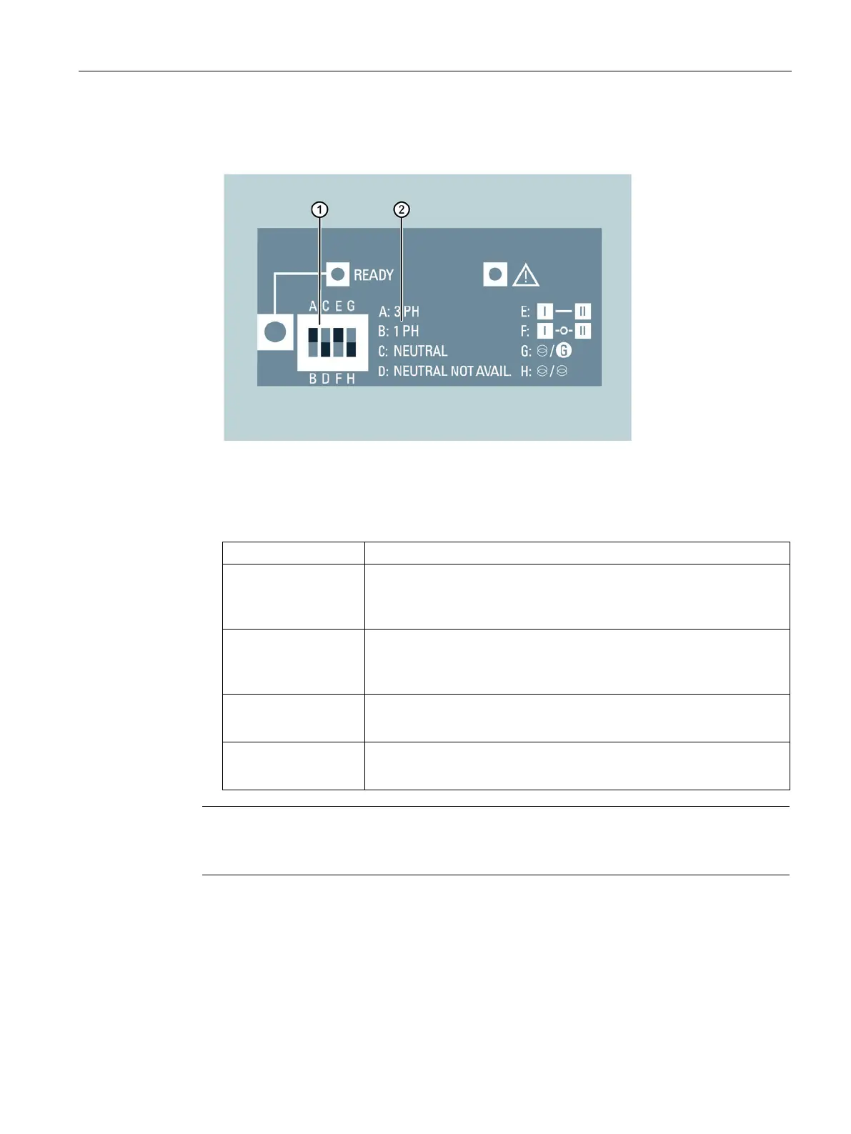
2. Set the position of the DIP switch manually with the screwdriver.
The different default options are explained, as well as the DIP switch.
DIP switch
Explanation of the defaults
Figure 7-18 DIP switch default
•
Three-phase network
•
: Single-phase network (with this setting, the DIP switch
is
inactive)
•
Three-phase 4-wire network with neutral: Enables recognition of
failure of the neutral conductor in the case of unbalanced loads
•
Three-phase 3-wire network without neutral
•
No additional delay in position O
•
Additional delay of 2 s in position O
•
Network / generator applications
•
Network / network applications
The "Ready" LED starts to flash green as soon as settings are made on the DIP switches.
The "Ready" LED does not go out until the settings are saved.