Connection
6.1 Network types
34 Manual, 08/2017, L1V30368969104A-02
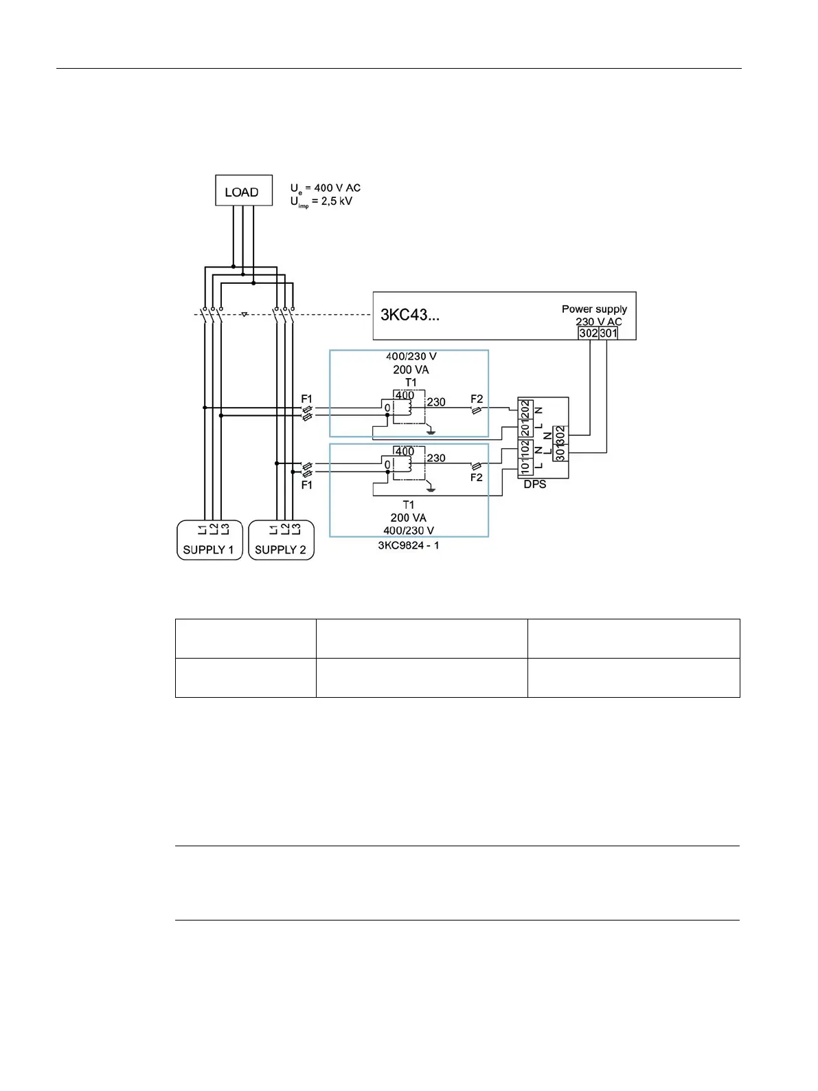
Circuit diagram for the 3KC4 transfer switching equipment - 3-pole transfer switching
equipment
Figure 6-3 Three-phase 3-wire network without neutral for the 3KC4 transfer switching equipment
F1 2 x 3NW6002-1
1 x 3NW7023
2 A, gG
F2 1 x 3NW6004-1
1 x 3NW7013
4 A, gG
With this arrangement there is no neutral conductor available. For this reason, the following
optional accessories can/must be used for establishing this network:
● 2 x autotransformer 3KC9824-1. For information, see the section titled Installing and
connecting an autotransformer (400 V / 230 V) (Page 79).
● 1 x dual power supply 3KC9625-1. For information, see the section titled Mounting and
connecting the dual power supply (DPS) (Page 77).
The F1 fuses must be installed as closely as possible to the tap.
The F2 fuses must be fitted as closely as possible to the output of the autotransformer.