Connection
6.1 Network types
36 Manual, 08/2017, L1V30368969104A-02
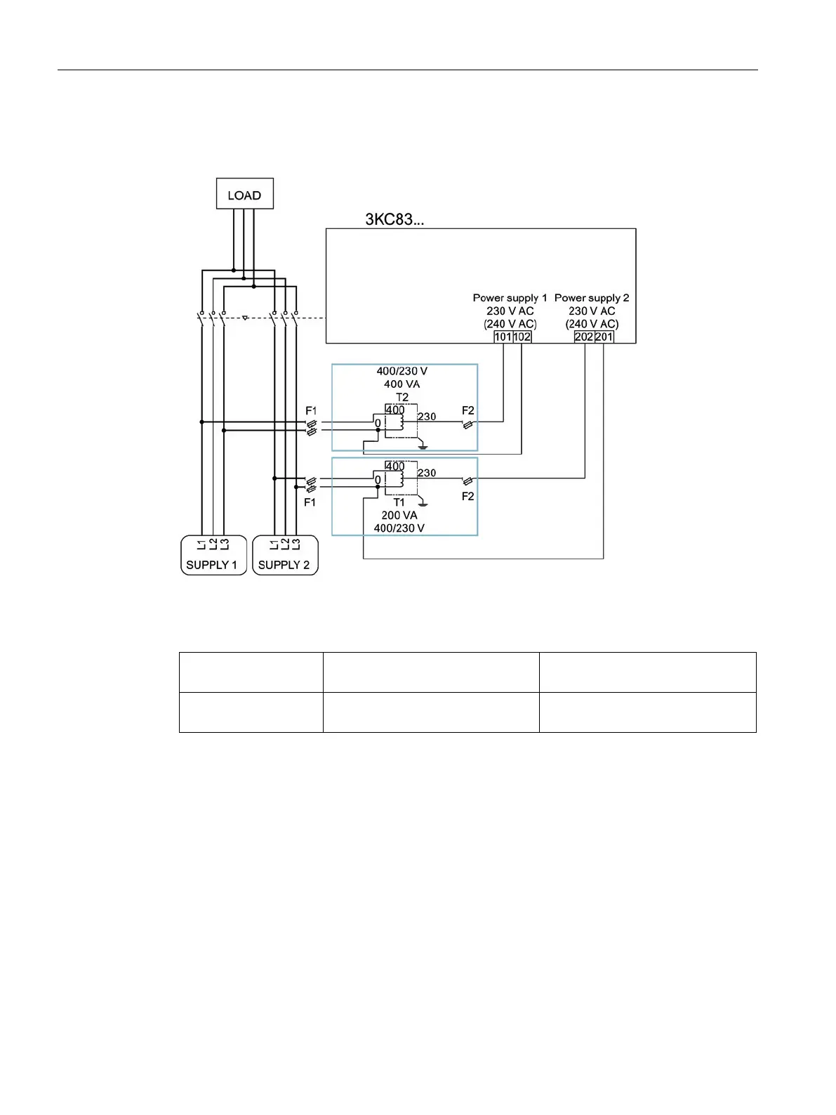
Circuit diagram for the 3KC8 transfer switching equipment - 3-pole transfer switching
equipment
Figure 6-5 Three-phase 3-wire network without neutral for the 3KC8 transfer switching equipment
(3-pole)
F1 2 x 3NW6002-1
1 x 3NW7023
2 A, gG
F2 1 x 3NW6004-1
1 x 3NW7013
4 A, gG
With this arrangement there is no neutral conductor available. For this reason, the following
optional accessories can/must be used for establishing this network:
● 2 x autotransformer 3KC9824-1. For information, see the section titled Installing and
connecting an autotransformer (400 V / 230 V) (Page 79).
● The auxiliary conductor terminal kit is required in the case of the 3-pole variant for
connecting the electronic module, and it must be mounted before connection to the
source. See the section titled Connecting the auxiliary conductor terminal 3KC9822-,
3KC9832- for a three-phase 3-wire network (3-pole) (Page 95).
The dual power supply (DPS) accessory is not required with the 3KC8 transfer switching
equipment since it is supplied with power via two inputs of the electronic module.