Connection
6.1 Network types
38 Manual, 08/2017, L1V30368969104A-02
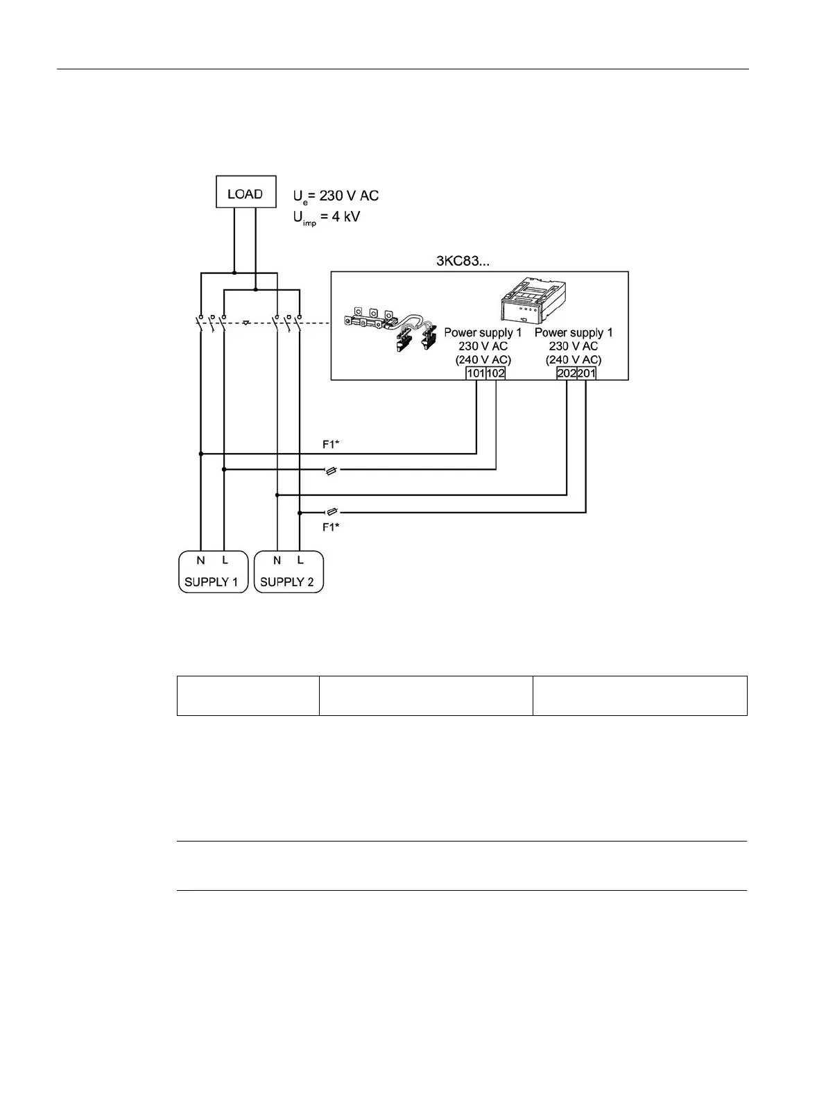
Circuit diagram for the 3KC8 transfer switching equipment - 3-pole transfer switching
equipment
* No fuse required if the power supply kit accessories 3KC9833-, 3KC9834- are used
Figure 6-7 Single-phase system without 3KC8 transfer switching equipment
F1 1 x 3NW6004-1
1 x 3NW7013
4 A, gG
The dual power supply (DPS) accessory is not required with the 3KC8 transfer switching
equipment since it is supplied with power via two inputs of the electronic module. Before
connecting, the pins 101/102 and 201/202 must be connected to the main circuit. This can
be done most easily with the 3KC9833-, 3KC9834- power supply kit. See the section titled
Connecting power supply kit 3KC9833-, 3KC9834- for single-phase network (Page 98) in this
regard.
The F1 fuses must be installed as closely as possible to the tap.