Manual, 08/2017, L1V30368969104A-02
205
The application areas for the 3KC4 and 3KC8 transfer switching equipment are described in
this chapter. The innovative solutions offered by the transfer switching equipment for
complex source requirements are described here. An appropriate, separate transfer
switching controller must be used with the 3KC4 transfer switching equipment for the
purpose of source monitoring and control.
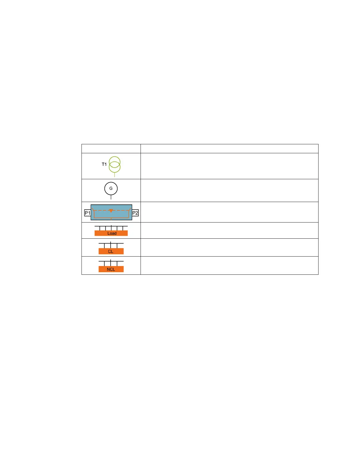
The symbols shown in the circuit diagrams have the following meaning:
Transformer (1)
Generator
Transfer switching equipment with the switches P1 and P2
Load
CL = critical load
NCL = non-critical load
The following tables show the behavior of the transfer switching equipment. The availability
of the sources (transformers or generators) is described by the following numbers:
● 1 = source available
● 0 = source not available
● x = source availability not defined as it is insignificant.
The switching states of the transfer switching equipment are described as follows:
● P1 = P1 switch closed
● P2 = P2 switch closed
● P3 = P3 switch closed, etc.
● x = insignificant (transfer switching equipment can be in any one of the three switching
states I, 0 or II).