Connection
6.2 Connecting the main circuit
Manual, 08/2017, L1V30368969104A-02
43
● Power supply is switched off
● Transfer switching equipment is in the "Manual" position
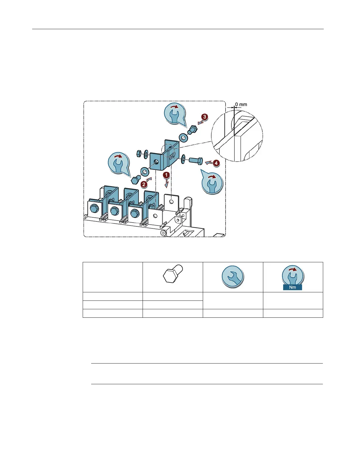
Figure 6-12 Mounting bridging bars for current ratings 250 A to 630 A
250 A M10 x 20 mm 17 20 ... 26
400 A M10 x 25 mm
630 A M12 x 30 mm 19 40 ... 45
1. Position the bridging bar on the connecting terminal.
2. Fix the first half of the bridging bar to the connecting terminal with the bolt and washer.
3. Fix the second half of the bridging bar to the connecting terminal with the bolt and
washer.
The two halves of the bridging bar must come into contact
before work step 4.
4. Connect the two parts of the bridging bar with 1 bolt, 2 washers and 1 nut in accordance
with the figure.