Connection
6.2 Connecting the main circuit
Manual, 08/2017, L1V30368969104A-02
67
Connecting versions 7 and 8
Requirements
● Main circuit is disconnected
● Transfer switching equipment is in the "Manual" position
● Copper bar connection kit is mounted
The bolt set required for mounting is not included with the transfer switch. You can find the
bolt set requirements in the following table:
7 (horizontal)
2000 … 2500 A
10 x H M12-55 6.8 20 x 10 x
8 (horizontal)
3200 A
10 x H M12-65 6.8 20 x 10 x
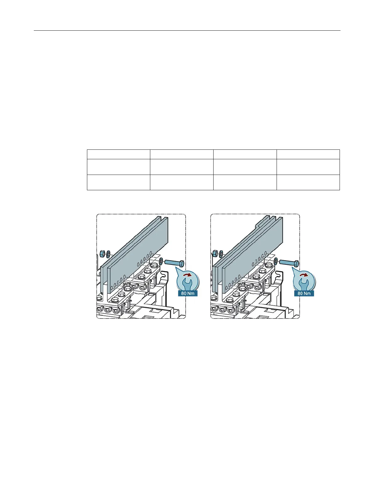
1. Mount the busbar with 10 bolts, 20 washers and 10 nuts on the transfer switching
equipment.
Figure 6-42 Connecting versions 7 and 8
2. Connect the mounted transfer switching equipment to the power supply systems.
– For the 3-pole type with 3 x the above listed bolt set.
– For the 4-pole type with 4 x the above listed bolt set.