Connection
6.3 Connecting the control circuit
76 Manual, 08/2017, L1V30368969104A-02
● Inputs and outputs are connected
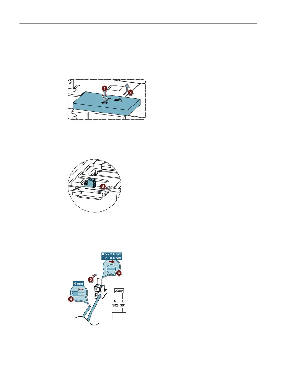
1. Press the pushbutton.
Figure 6-54 Removing the cover cap
2. Slide the flap carefully backwards and remove it.
Inputs 301 and 302 are now accessible.
3. Remove the connector
Figure 6-55 Remove the connector
4. Prepare the supply lines in accordance with the figure: N on 302, L on 301.
5. Connect the supply lines with the connector
6. Tighten the terminals.
Figure 6-56 Connecting supply cables with connector