Connection
6.3 Connecting the control circuit
Manual, 08/2017, L1V30368969104A-02
83
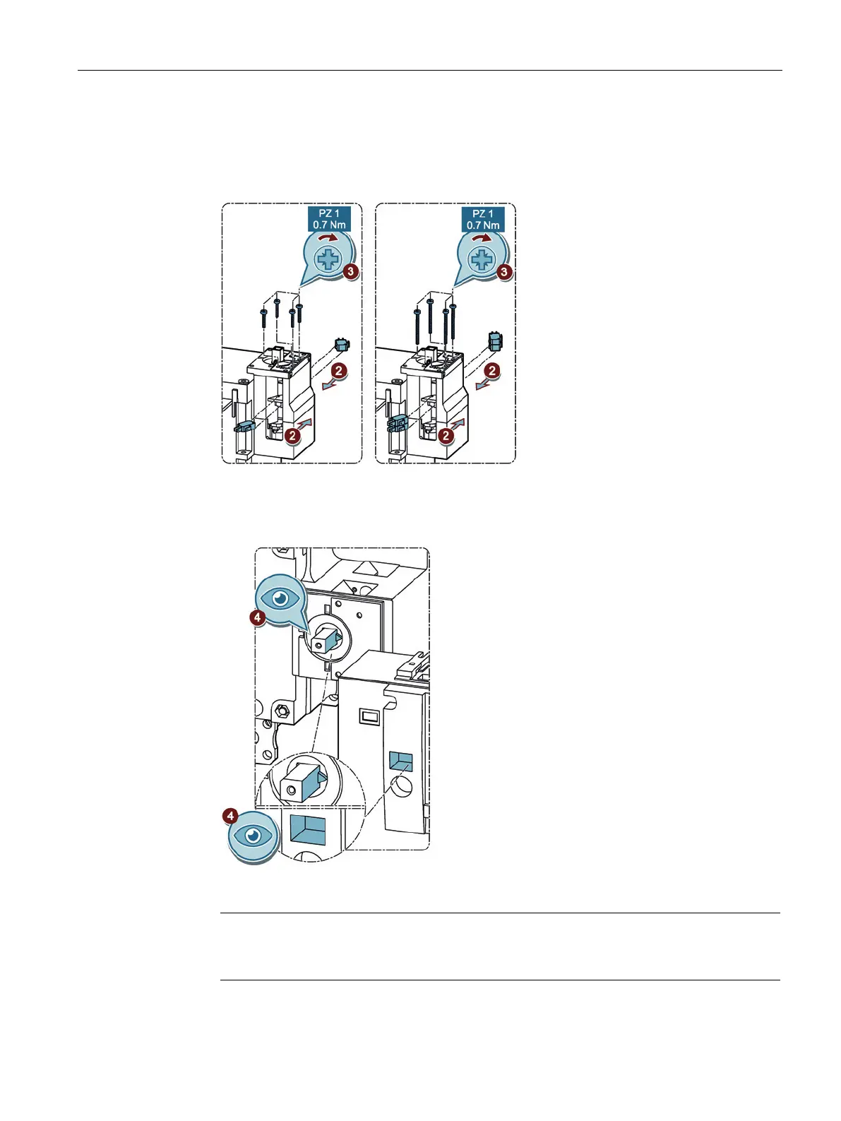
3. Fix the auxiliary switch to the transfer switching equipment.
– When installing 1 auxiliary switch use 4 short bolts M3 x 18 mm.
– When installing 2 auxiliary switches use 4 long bolts M3 x 30 mm.
Figure 6-65 Installing auxiliary switches
4. After installing the auxiliary switch, place the motor operator on the transfer switching
equipment again.
Figure 6-66 Installing the motor operator on the transfer switching equipment
Make sure the switch position shown in the auxiliary switch display is identical to that of
the transfer switching equipment.
5. Install the motor operator on the transfer switching equipment with the bolts.