Configuring
6.2 Configuring the CPU
Distributed I/O system
144 System Manual, 12/2016, A5E03576849-AG
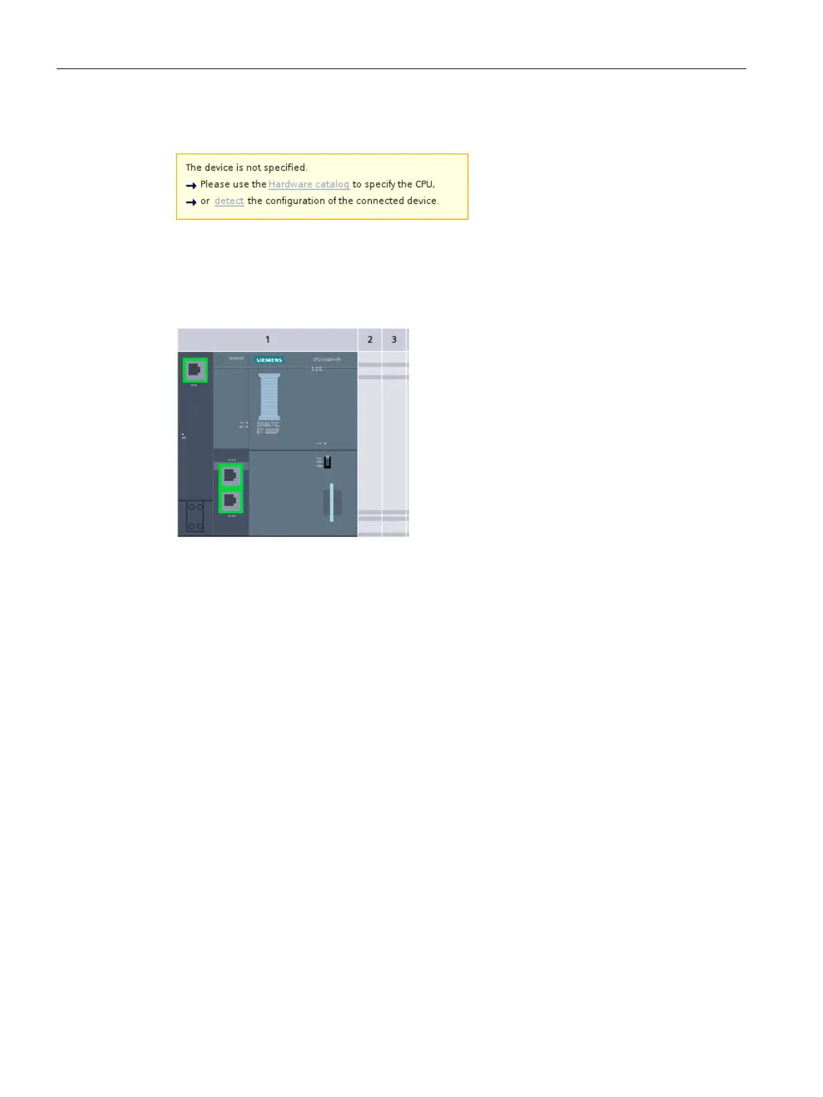
You can also double-click the CPU and click "Detect" in the message.
Figure 6-3 Hardware detection message in the device view
After you have selected the CPU and the PG/PC interface in the "Hardware detection for
PLC_x" dialog and have clicked the "Detect" button, STEP 7 loads the hardware
configuration including the modules from to the CPU into your project.
Figure 6-4 Result of the hardware detection in the device view
STEP 7 assigns a valid default parameter assignment for all modules. You can change the
parameter assignment subsequently.
Properties of central modules
The properties of the CPUs have special significance for system behavior. You can set the
following for a CPU using STEP 7:
● Startup behavior
● Parameter assignment of the interface(s), for example, IP address, subnet mask
● Web server, e.g. activation, user administration, and languages
● Cycle times, e.g. maximum cycle time
● System and clock memory
● Protection level for access protection with assigned password parameter
● Time-of-day settings (daylight saving time/standard time)
The properties that can be set and the corresponding value ranges are specified by STEP 7.
Fields that cannot be edited are grayed out.