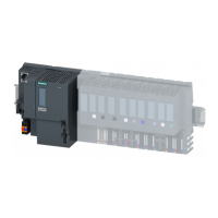
Distributed I/O system
8 System Manual, 12/2016, A5E03576849-AG
Preface ................................................................................................................................................... 4
1 Guide to documentation ........................................................................................................................ 13
2 System overview ................................................................................................................................... 17
2.1 What is the SIMATIC ET 200SP distributed I/O system? ...................................................... 17
2.2 What are fail-safe automation systems and fail-safe modules? ............................................ 20
2.3 How are SIMATIC Safety F-systems structured with ET 200SP? ......................................... 21
2.4 Components ........................................................................................................................... 25
3 Application planning .............................................................................................................................. 32
3.1 Selecting the BaseUnit for I/O modules ................................................................................. 36
3.1.1 Digital, fail-safe, communication, technology or analog modules without temperature
measurement ......................................................................................................................... 36
3.1.2 Analog modules with temperature measurement .................................................................. 37
3.2 Selecting motor starters with a suitable BaseUnit ................................................................. 38
3.2.1 Selecting a BaseUnit for motor starters ................................................................................. 38
3.2.2 Selecting the motor starter ..................................................................................................... 39
3.2.3 Selecting accessories for motor starters ................................................................................ 40
3.3 Hardware configuration .......................................................................................................... 41
3.4 Forming potential groups ....................................................................................................... 43
3.4.1 Basics ..................................................................................................................................... 43
3.4.2 Forming potential groups with AC I/O modules ..................................................................... 47
3.4.3 Forming potential groups with fail-safe modules ................................................................... 49
3.4.4 Forming potential groups with motor starters ........................................................................ 50
3.5 Configuration examples for potential groups ......................................................................... 52
4 Installation ............................................................................................................................................ 54
4.1 Basics ..................................................................................................................................... 54
4.2 Installation conditions for motor starters ................................................................................ 58
4.3 Mounting the CPU/interface module ...................................................................................... 60
4.4 Installing the CM DP communication module ........................................................................ 62
4.5 Mounting BaseUnits for I/O modules ..................................................................................... 64
4.6 Mounting and dismantling BaseUnits for motor starters ........................................................ 66
4.7 Installing the server module ................................................................................................... 68
4.8 Mounting further accessories for motor starters .................................................................... 69
4.8.1 Mounting the cover for the 500 V AC infeed bus ................................................................... 69
4.8.2 Mounting the mechanical bracket for the BaseUnit ............................................................... 71
4.8.3 Mounting the BU cover .......................................................................................................... 74
 Loading...


