Wiring
5.7 Wiring BaseUnits for I/O modules
Distributed I/O system
90 System Manual, 12/2016, A5E03576849-AG
Wiring BaseUnits for I/O modules
Introduction
The BaseUnits connect the ET 200SP distributed I/O system to the process. The following
versions of the BaseUnits can be used:
● BaseUnits (with light-colored terminal box) for opening a potential group: BU..D
● BaseUnits (with dark-colored terminal box) for extending the potential group: BU..B
● BaseUnits with additional AUX terminals or additional terminals: BU..+10..
● BaseUnits with integrated thermal resistor for compensation of the reference junction
temperature when connecting thermocouples: BU..T
Measuring probe (suitable probes: 1 mm diameter, length ≥ 10 mm while observing the
permitted voltage category)
Holder for shield connection
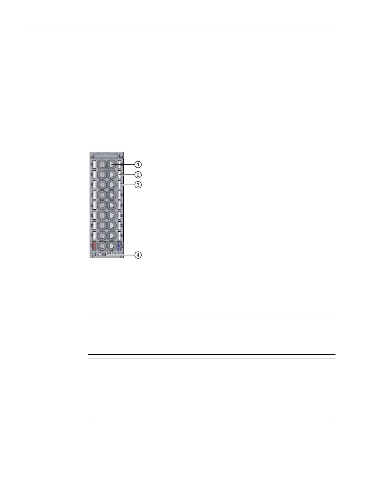
Figure 5-5 View of the BaseUnit
Note
The pin assignment of the BaseUnit depends on the connected I/O module. Information
on the BaseUnits and I/O modules can be found in the associated manuals.
Replacement of the terminal box on the BaseUnit is described in the section
Replacing
the terminal box on the BaseUnit
(Page 243).
Note
Special terminal designations in the wiring and block diagrams of the I/O
modules/BaseUnits
•
: Reserve, these terminals must remain unconnected so that they can be used for
future expansions
: Not connected, these terminals have no function. However, they can be
connected to potentials specifically defined for a module, for example, for the laying
unused wires.