Application planning
3.4 Forming potential groups
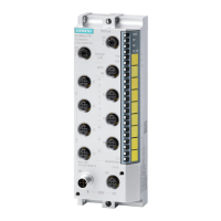
Distributed I/O system
48 System Manual, 12/2016, A5E03576849-AG
Connect the required alternating voltage for the AC I/O modules directly at the BaseUnits
BU20-P12+A0+4B (terminals 1L, 2L/1N, 2N). Insert the AC I/O modules on the BaseUnits.
Note
Placing the BaseUnits for AC I/O modules
If you insert an AC I/O module as the first I/O module, a BaseUnit BU20
-P12+A0+4B can be
the first BaseUnit to the right of the CPU/interface module in the ET 200S
P configuration.
The requirement is that you use a CPU as of V3.0 or IM 155
-6 (as of V3.0).
The BaseUnits BU20-P12+A0+4B do not monitor the connected alternating voltage.
Please note the information on limiting the overvoltage and power rating in the AC I/O
module manuals.
Remember to take the BaseUnit type into account during configuration.
BaseUnits with DC I/O modules
BaseUnits BU 20-P12+A0+4B with AC I/O modules
Figure 3-4 Placing the BaseUnits for the AC I/O modules