R 02/92
General Function Description
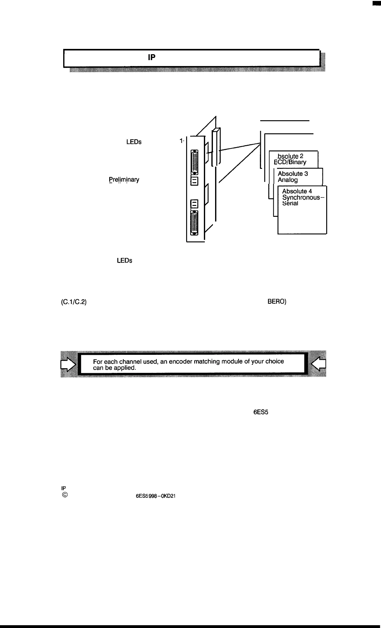
1.1
Design of the
1P
241
Basic module
Matching module
Synchronization
LEDs
for channel
1
<
for channel 2
<
Channel 1
(50-way sub D)
{
Prelimina~
contact 1
Preliminary contact 2
P 24 V external
M external
Channel 2
(50-way sub D)
{
o
0
/
1111
;
“
:
El
,
El
‘
II
/
i
I
m
I
Incremental
I
Absolute 1
Excess–3 Gray
I
4
bsolute
2
CD/Binary
Absolute 3
Analog
r
Absolute 4
Synchronous–
Serial
Synchronization
LEDs
–
Channel 1
—
Preliminary contacts –
(c,l/c.2)
24 V external
—
Channel 2
—
go off after synchronization of the respective channel
for connection of an encoder (actual value)
for synchronization (reference point method)
with incremental encoders per channel (e.g.,
BERO)
voltage supply for encoder and matching modules
for connection of an encoder (actual value)
The connections preliminary contact 1/2 and P/M are intended for FASTON connectors (2,4 mm x
0.8 mm).
These inputs are designed as screw connections starting with MLFB
6ES5
241 –lAA12.
1–1
1P
241 Equipment Manual
@
Siemens AG 1989, Order No: 6ES5
998-0KD21
Artisan Technology Group - Quality Instrumentation ... Guaranteed | (888) 88-SOURCE | www.artisantg.com

 Loading...


