R 02/92
Matching Module 2 for Absolute Encoders
5.3
Putting into Operation
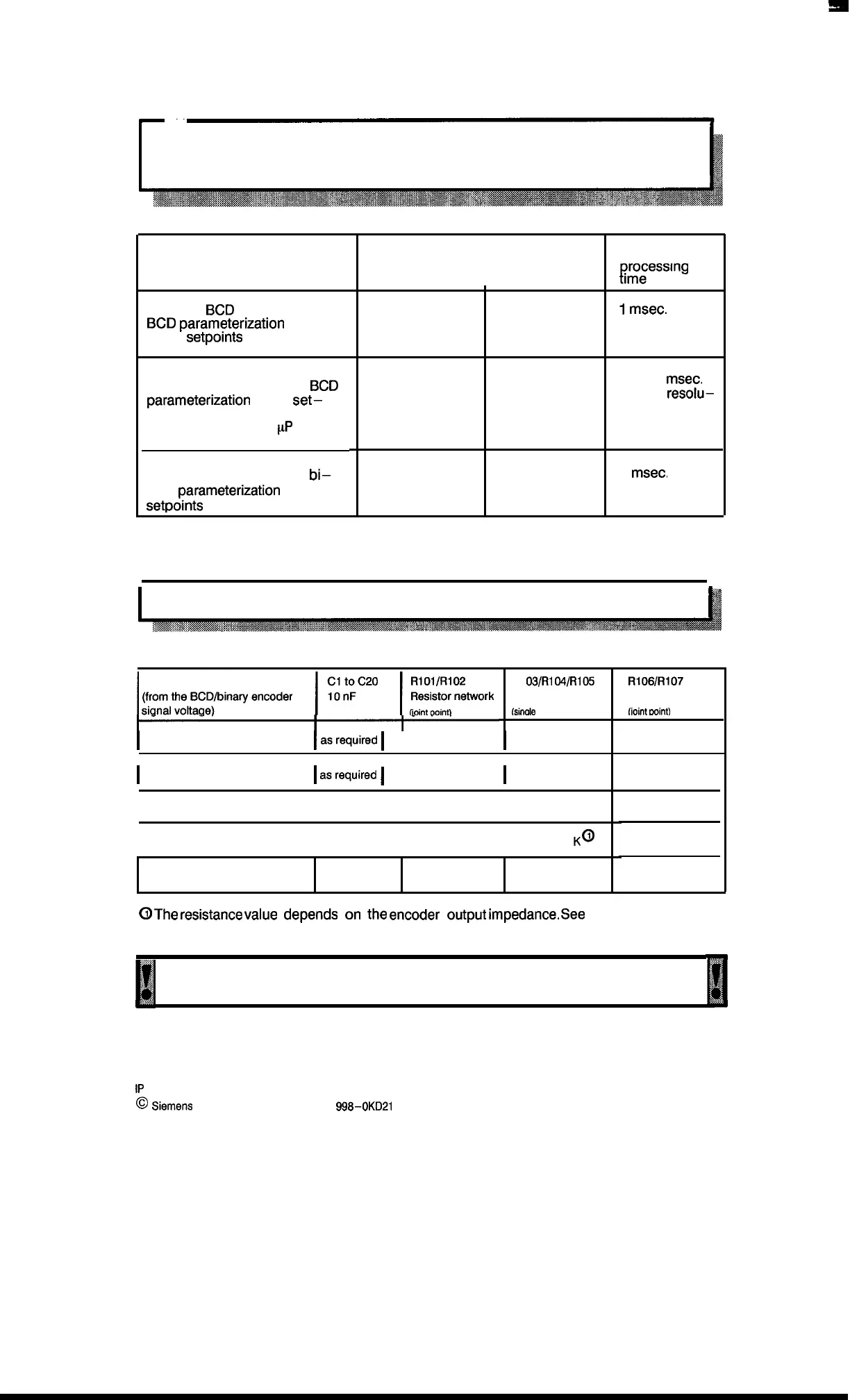
5.3.1 Setting the Operating Mode
DIP switch S1
Contact 1
I
Contact 2
Absolute
BCD
encoder and
BCD
parameterization
of the
setpoints
closed closed
Absolute binary encoder
(maximum of 17 bits) and
BCD
parameterization
of the
set–
points
(conversation by the
pP
of the
basic module)
Absolute binary encoder
(maximum of 20 bits) and
bi–
nary
parameterization
of the
setpoints
open
closed
closed
closed
Typical .
IRess’ng
1
msec.
3 to 13
msec.
(higher
resolu–
tion = increased
time)
1
msec.
5.3.2 Conditioning the Input Levels
L%%:::’binayencoder
l:;’;c20
l,i%!FOrk
Input voltage
RI
03/Rl
04/R105
Resistor network
(sinale resistor)
I
5“
I
asrequired
I
omitted
I
Wire jumpers
I
12V
I
asrecluired
I
omitted
I
899-3-R2K
I
15 v
I
as required
I
omitted
I
699=3-R 3,3 K
I
24 V
I
as required
I
omitted
I
899–3–R ? K@
Open Collector
as required
899–1 -R 8,2 K
Wire jumpers
@
The
resistance
value
depends
on
the
encoder
output
impedance.
see
nol
RI061RI07
Resistor network
(ioint
mint)
omitted
899–1 –R 1,5 K
899-1 –R 1,5 K
899-1 –R 1,5 K
899-1 -R 1,5 K
on next page.
Small disturbances that occur in spite of correct wiring and shielding can be
corrected with the capacitors Cl to C20.
1P
241 Equipment Manual
@
.%I?WJIIS
AG 1989, Order No.: 6ES5
998-0KD21
5–3
Artisan Technology Group - Quality Instrumentation ... Guaranteed | (888) 88-SOURCE | www.artisantg.com

 Loading...


