General Function Description
Example 2:
R
02/92
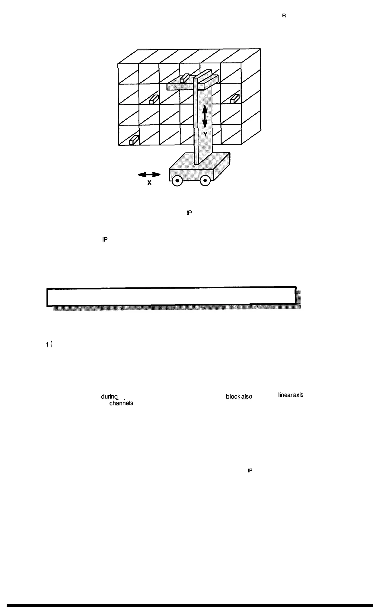
Example 2: Simple Positioning in a High Shelf Storage System
In this case the actual positions are transferred to the
1P
241 via absolute value encoders as other-
wise long distances would have to be covered by “reference point traversing” in the event of a
voltage cut off.
In example 2, the two
1P
241 channels are used for acquisition of the individual coordinates (posi-
tions).
When the work piece reaches its designated coordinates (i.e., the cams), the respective motor is
stopped by the programmable controller.
1.7.2 Conditions
The linear axis function can be transferred to the module in one of the three following ways:
1
J
2.)
3.)
After each power on, this function is automatically selected; the same is applicable after each
voltage cut off (no buffering on the 1P).
After parameter assignment by means of the standard function block FB 156, the software
reset in this block presets each channel to linear axis. Consider allocation of the data block (IP
241)!
A
software reset
during
operation without the standard function
block
also
causes a
linear
axis
presetting for both
channels.
This means that in the relative byte 4 of the module, the settings must be: read bit = “1”, actual
bit = “1”, and end bit = “1” (see section 9.6).
1 – 16
1P
241 Equipment Manual
@SiemensA(31989, Order No: 6ES6998-0KD21
Artisan Technology Group - Quality Instrumentation ... Guaranteed | (888) 88-SOURCE | www.artisantg.com

 Loading...


