R 02/92 Matching Module 3 for Absolute Encoders
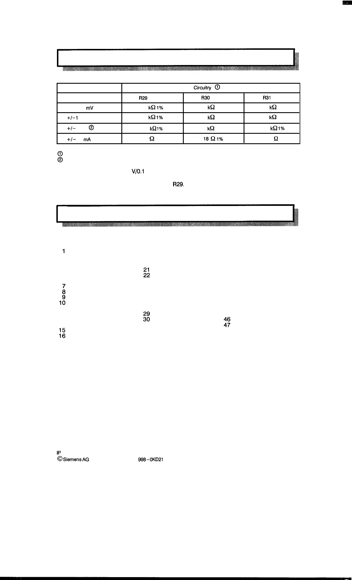
6.3.2 Matching the Measured Value Ranges
Measuring range
Circuit~
0
R29
R30
R31
+/– 100
mV
1
I@
1’%
1
k~
1% 100
k~
1%
+1–
1
v
10
k~
1’%.
9,1
k~
1%
100
k~
1%
+/–
10
v
@
10
k~
1’%.
5,1
k~
1%
10
k~
17.
+1-
20
mA
25
~
1%
18
~
IYo
500
Q
1%
@
See layout plan for analog module, section 6.3.4.
@
State as delivered.
The reference voltage of + 10
V/O.l
A is available at pin 18 of the front connector.
The input impedance at pin 1 corresponds to
R29.
6.3.3 Connector Pin Assignment
Assignment of the sub D connector pins (channel 1 or 2)
1
U or I (+) connection
18 + 10 V Reference voltage
2 Ground reference voltage 19
3
20
4
5
;;
6
23
24
:
25
26
1:
27
11
28
12
13
::
14
31
32
;;
33 M
17 M
Pins 17/33/50 are parallel and thus can be used alternatively.
34
35 U or 1 (–) connection
36
37
38
39
40
41
42
43
44
45
%
48
49
50 M
1P
241 Equipment Manual
~
Siemens
AG
1989, Order No.: 6ES5 998-0KD21
6–5
Artisan Technology Group - Quality Instrumentation ... Guaranteed | (888) 88-SOURCE | www.artisantg.com

 Loading...


