Operating Instructions
R 02/92
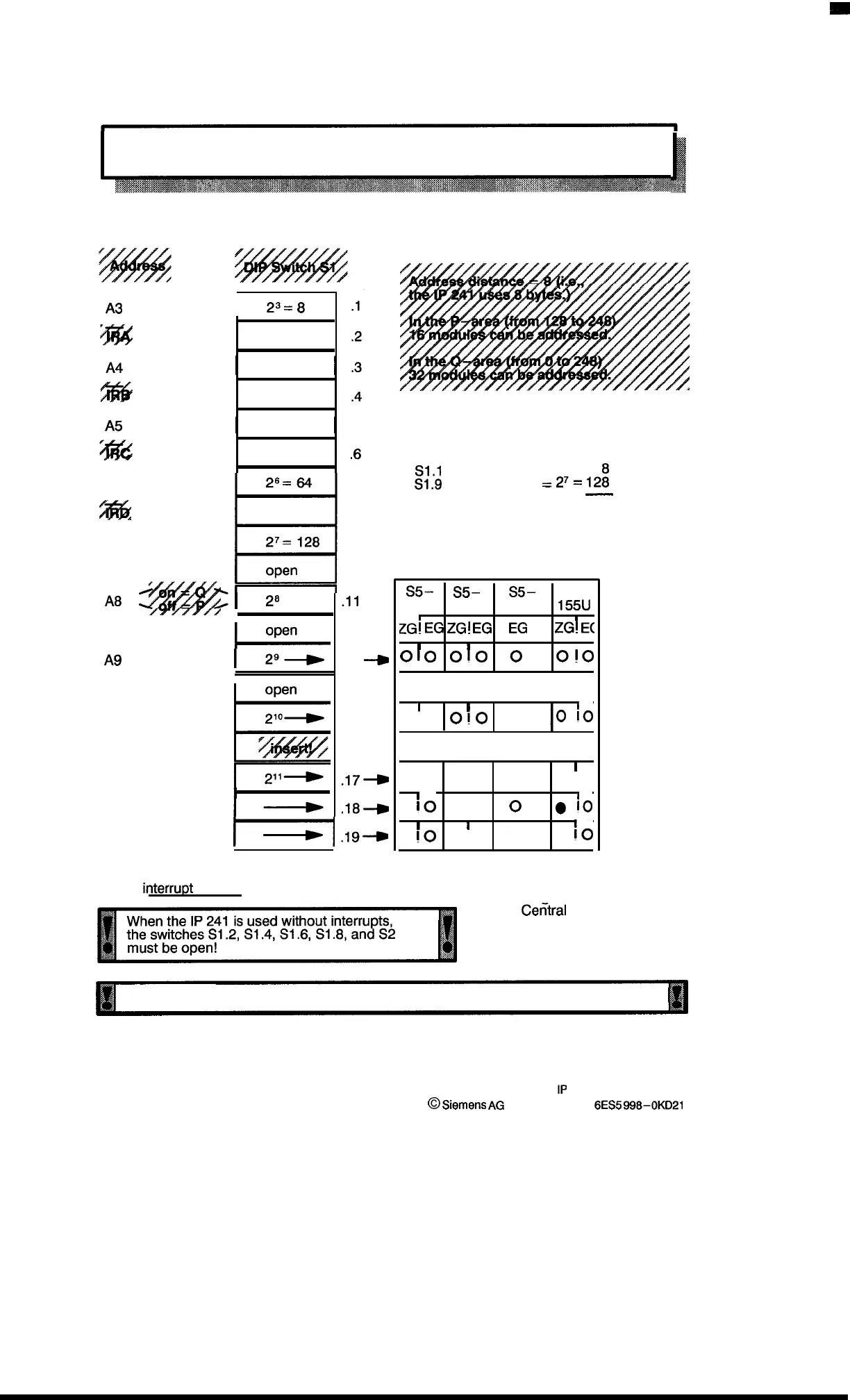
2.2 Settings for the Module Address and the Interrupt Lines
(See the layout for the basic module, section 2.1.)
A3
.
4!%
A5
A6
%ft6
.
A7
A9
AlO
PESP– Break point
Al 1
Al 1– Break point
I
23=
8
I
2
4
=16
I
I
2
5
=32
I
I
2s
1
.5
.6
.7
.8
.9
10
Example:
“136” is set as module address.
S1.1
insetted: A3 = 2
3
=
S1.9 inserted:
A7 =
27=
lpi
136
-
.11
.12
.13
-g
.14
.15-,
.16
.17+
,18-0
A8–A11 Break point
ml,+
Sections 2.3 to 2.8 show the settings
for the
interru~t
lines.
s5–
s5–
s5–
s5-
115U
135U
15ou/s
155U
zGi
EG
ZGI
EG
1
EG
I
ZGI
E(
I
1
I
c)
10
010
0
010
open
I
1
010
010
0
0
:0
inser!
I
I
I
010
010
0
010
●
k)
●
!0
()
g
10
1
I
●
10
●
10
o
●
:0
S5 = Programmable Controller
ZG =
Cetitral
unit
EG = Expansion unit
O = open
. = inserted
The Q–area cannot be addressed in the central unit.
2–2
1P
241 Equipment Manual
@
Siemens
AG
1989, Order No.:
6ES5
988-0KD21
Artisan Technology Group - Quality Instrumentation ... Guaranteed | (888) 88-SOURCE | www.artisantg.com

 Loading...


