R02/92
Matching Module 4 for Absolute Encoders
7.1
Function Description
The serial actual values of an encoder with synchronous–serial interface according to RS 485 or
RS 422 are converted to
~arallel
information on the encoder
matchina
module and are transferred
to the output memory
of-the
basic module.
%codel
LOOP
IN +
LOOP
OUT +
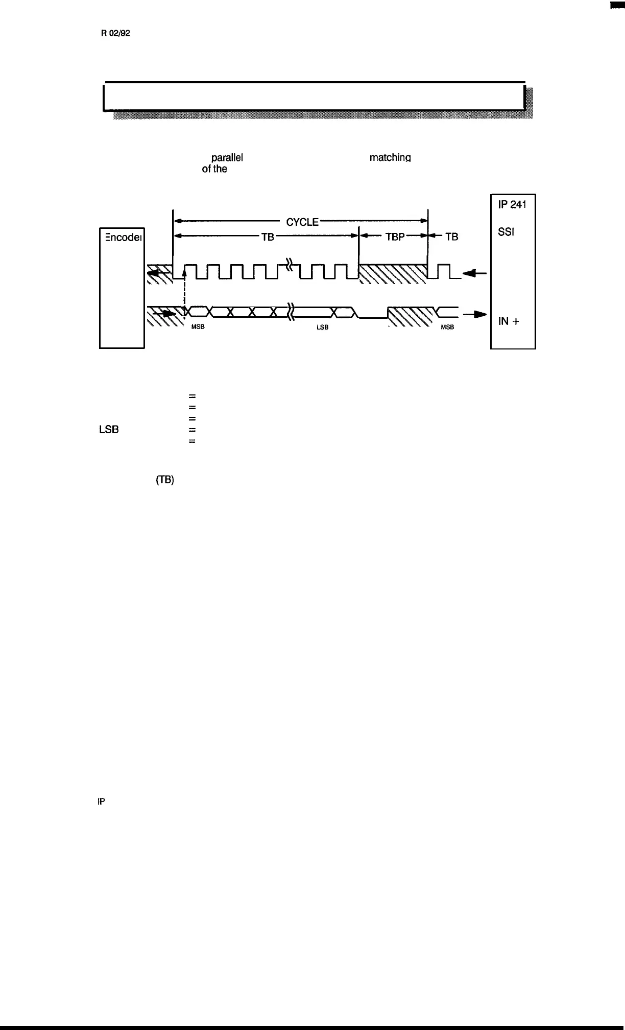
Time sequence of a read cycle
,
i
SSRS2JMSSX
x
x
x
‘{
4
\\
x
LSS
KS
IP241
Ssl
Module
LOOP
OUT+
LOOP
IN+
LOOP OUT + =
LOOP IN + =
TB
=
TBP
=
MSB
=
LSB
=
KB
=
OUTPUT “+ “ SEND CLOCK PULSE GROUP
INPUT “+” ACTUAL ENCODER VALUE
CLOCK PULSE GROUP (NUMBER OF CLOCK PULSES) parameterizable
CLOCK PULSE GROUP INTERVAL (DEFINED BY HARDWARE)
MOST SIGNIFICANT BIT
LEAST SIGNIFICANT BIT
CONTROL BIT
The encoder matching module fetches the actual encoder values by cyclic emission of a clock
pulse group
(TB)
and transfers them to the basic module via the output memory.
A clock pulse group is a package of single pulses.
The number of clock pulses in a clock pulse group depends on the encoder resolution.
1P
241 Equipment Manual
@SiemensA(31989, Order No,: 6ES5998-0KD21
7–1
Artisan Technology Group - Quality Instrumentation ... Guaranteed | (888) 88-SOURCE | www.artisantg.com

 Loading...


