Ff
02/92
Matching Module 4 for Absolute Encoders
7.3.7 Connector Pin Assignment
Assignment of the sub D connector pins (channel 1 or 2)
;
3
4
5
6
7
8
1;
11
12
13
14
;:
17
Pins
LOOP
OUT–
18
34
35 LOOP OUT+
;:
36
21
22
23
24
25
26
:;
LOOP IN +/Opto coupler
29 LOOP iN+/Receiver
LOOP IN –/Receiver
30 SENSE+
31
37
38
::
41
42
43
44
45 LOOP IN–/Opto coupler
46
47
SENSE–
32 -t- 5
VI12
VI15
v 48 -f- 5
VI12
VI15
V
SENSE– 33 M
:4
;
24
V
Output
M
15/1 6 as well as pins 32/48 and pins 17/33/50 are parallel and can be used alternatively.
LOOP OUT = Clock pulse group output
LOOP IN
= Data input
SENSE+
= Sense(+) output for control of encoder power supply
SENSE–
= Sense(–) output for control of encoder power supply
I
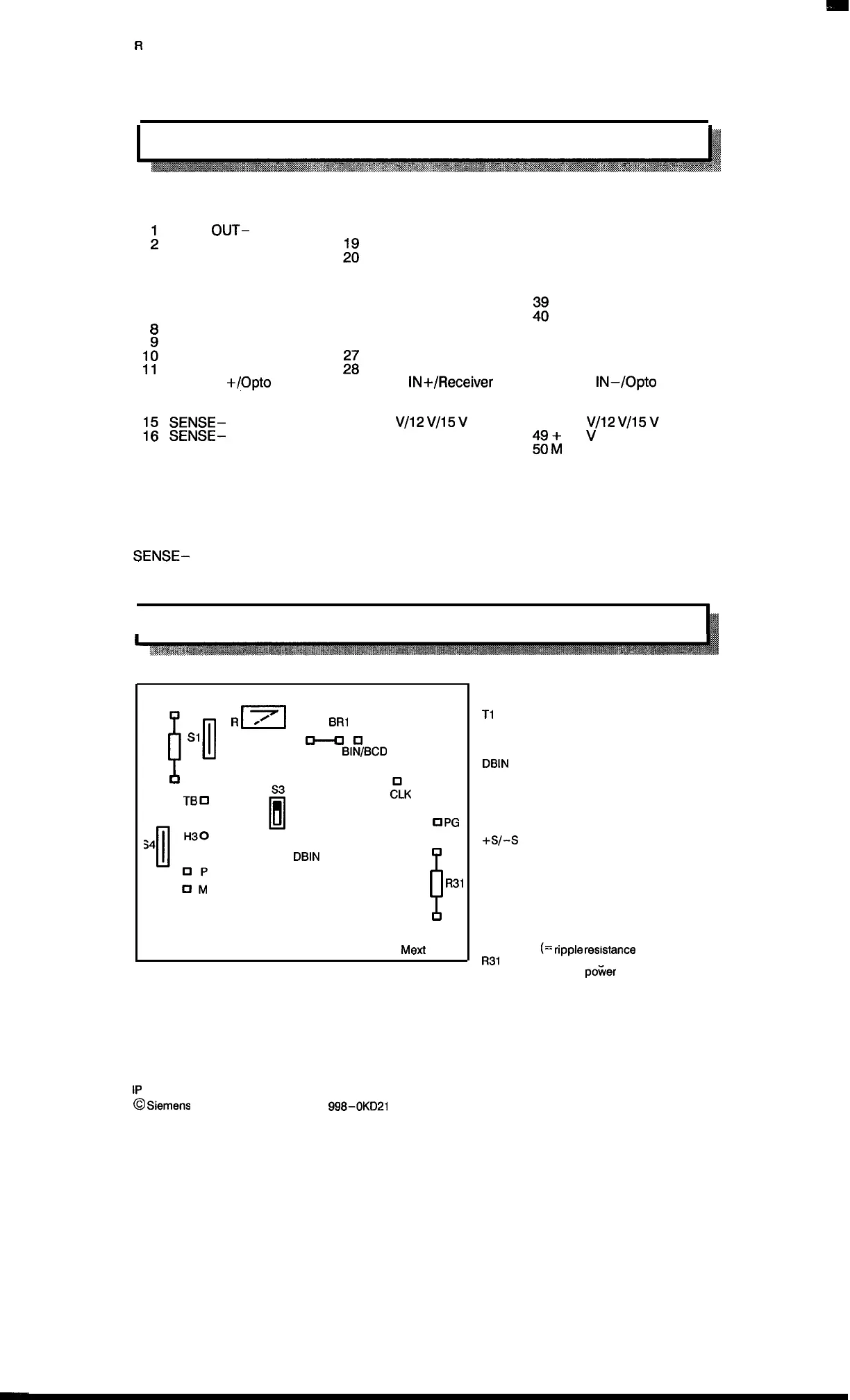
7.3.8 Layout
‘b
S2
T1
~11
o
n
❑
R
~
BR1
S1
R2
~n
Gray
BIN/BCD
b
H20
TBCI
UM
S5
El
— .2
—
.1
❑
DBIN
FLK
UPG
❑ +s
b
R31
/l
cl-s
Mexl
❑
TB =
T1
=
CLK =
DBIN
=
P=
M=
PG =
+s/-s
=
HI =
H2 =
H3 =
R2 =
R31
=
Measuring point for clock pulse
groups to the encoder
Measuring point for clock pulse
from the basic module
Measuring point preprogrammed
clock pulse
Measuring point after gray
binary conversion
Measuring point 5 V supply
M–potential (ground)
Measuring point configured
encoder supply
Measuring points for sense
voltages
LED indicates: Enable for
transmitting clock pulse groups
LED indicates: If continuously lit
the input signal is missing.
Data flow via opto coupler is
available
Conditioning resistance
(=
ripple
res@ance
of cable)
Conditioning resistance for
encoder poker supply
The layout shows the position of the configurable elements, jumpers, and switches.
1P
241 Equipment Manual
@
Siemens AG 1989, Order No.: 6ES5
998-0KD21
7 – 13
Artisan Technology Group - Quality Instrumentation ... Guaranteed | (888) 88-SOURCE | www.artisantg.com

 Loading...


