Matching Module 4 for Absolute Encoders R 02/92
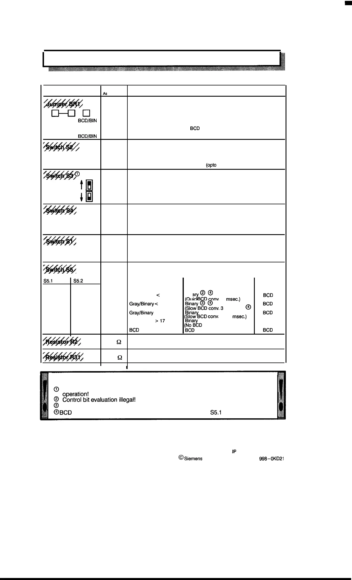
7.3.9 Configuration At–A-Glance
Element
As
delivered
Function
C1-clcl
●
Connection to gray code encoders
Gray
BCD/BIN
❑ o-cl
Connection to encoders with
BCD
or binary code
Gray
BCD/BIN
?
Input interface RS 422 or RS 465 with:
Position “R” closed
●
Encoder connection at receiver
Position “O” closed
Encoder connection via current loop
(opto
coupler)
W*
in position
[
to
●
Incrementing values for encoder shaft in “right” rotation
in position
In
Incrementing values for encoder shaft in “left” rotation
/.
open
●
Control bit from encoder not available
closed
Control bit from encoder available
open
●
Encoder presents fault message “high” for control bit evaluation
closed
Encoder presents fault message “low” for control bit evaluation
T’
Selection of code types for actual encoder values by “BR1”
(see section 7.3.1)
S5.1
S5.2
Actual encoder value Transfer to basic module
Transfer
@@
to PLC:
open
open
Gray/Binary < = 10 bits
Bina
“7
BCD
(QUIC
BCD
conv.
1
msec.)
closed
open
●
Gray/Bina~
e
= 10 bits
&%?’B$?D~nv.3msec.
)
@
:::
closed open
●
Gray/Binaqr
to 17 bits
(?I%%CD
conv.
3-13
msec.)
closed closed
Gray/Binary
>17
bits
Binary
~~}%D
conversion possible)
closed closed
BCD
BCD
100
Q
Matching as required (see section 7.3.5)
1.3 k
~
Matching as required (see section 7.3.2)
I
I
Jumper or switch settings deviating from those shown above are illegal!
@
Internally a two’s complement representation is used; no switch–over during
@
Avoid long processing time!
~
@
BCD
conversion can be switched off by closing switches
S5.1
and S5.2.
7 – 14
IP
241 Equipment Manual
@
Siemens AG 1989, Order No.: 6ES5
998-0KD21
Artisan Technology Group - Quality Instrumentation ... Guaranteed | (888) 88-SOURCE | www.artisantg.com

 Loading...


