General Function Description
R
02/92
I
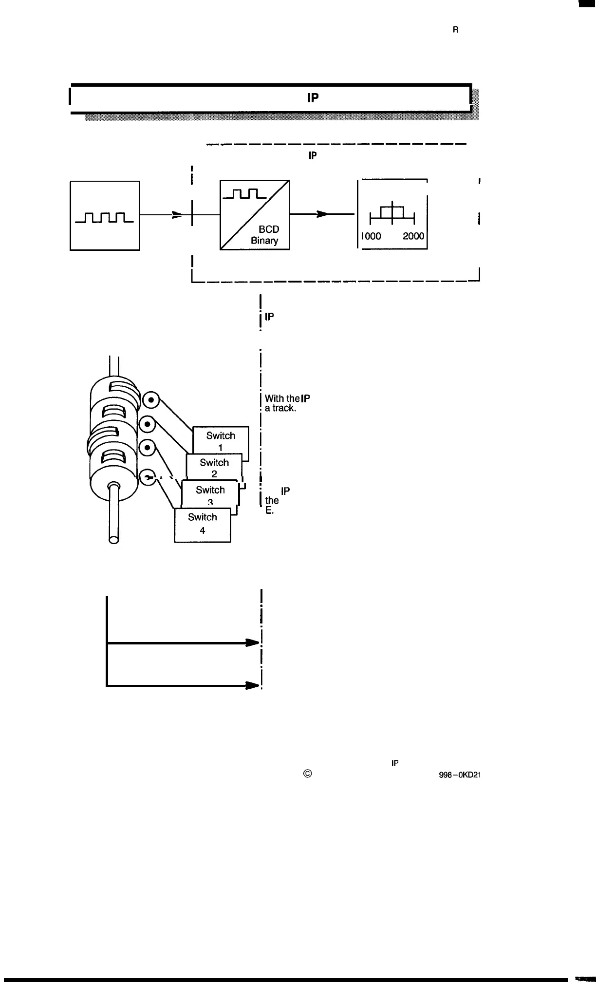
1.6 General Operating Principle of the
1P
241
p
li
;~..
t
.:.:..,
r
————.————.———.—————
1P
241
1
I
i
Matching module
I
_ll_ll
-
-
F
r
I
I
I
L–––__
I
Electromechanical cam control system
I
Basic module
i
1
1500
I
i
J
ml
i
Track
I
I
000
2000
I
I
I
——————————————
J
1P
241 = electronic cam–operated controller
l\
W
A
\
,
1
,1
1
w-,,
%v:ch
~
~
I
.
~~:::~e
1P
241, each switch corresponds to
A maximum of 16 tracks per channel is possible.
If “single channel” operation is selected, max-
imum of 32 tracks is possible (operation with par-
allel connection)
)3
.
Switch
I
4
i
.
Each cam corresponds to an electronic cam on
the
1P
241; its position is defined by specifying
~e
respective initial value A and the end value
I
i
I
.
I
>1
.
I
J
Linear axis operating mode
(see section 1 .7)
Rotary axis operating mode
(see section 1.8)
1–6
1P
241 Equipment Manual
@
Siemens AG 1989, Order No: 6ES5
998-0KD21
Artisan Technology Group - Quality Instrumentation ... Guaranteed | (888) 88-SOURCE | www.artisantg.com

 Loading...


