R 02/92
Matching Module 3 for Absolute Encoders
6.3 Putting into Operation
6.3.1 Parametrizing the Hysteresis
When the
1P
241 is operated with the matching module (analog) 3forabsolute encoder, depend-
ing on the ripple of the voltage applied, fluctuations of the actual values may occur.
In order to correct this deficiency (starting with firmware version
V7.0),
a hysteresis value can be
preset as follows:
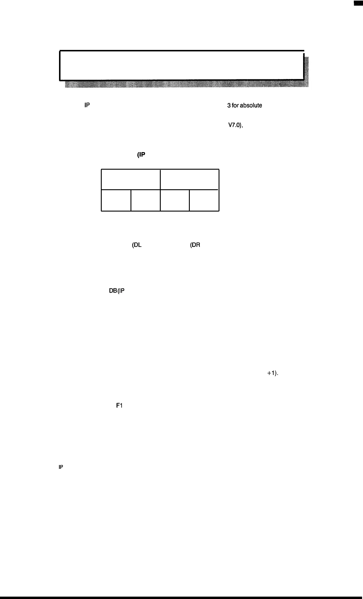
1. Presetting the data block (IP 241) by using the standard function block
DW 177
Enable channel 1
Enable channel 2
DW 178
10‘
10° 10’ 10°
The hysteresis values in DW 178 are given in BCD code.
If the enables for channel 1
(DL
177) or channel 2
(DR
177) are set with KH = FF, the hysteresis
value of the respective channel is not transferred to the module.
2. Parameterization of the module by FB 156
After presetting the
DB
(IP
241 ), the standard function block FB 156 is usually called in case there
is a new start.
3.
1.
2.
3.
4.
For a parameter assignment without the standard function block proceed as follows:
Specify the channel number by entering the track number into byte O
(module address + O)
Track O to 15 corresponds to channel 1
Track 16 to 31 corresponds to channel 2
Specify the hysteresis value (00 to 09) by entry into byte 1 (module address +1).
Byte 2 and byte 3 remain free.
Enter the identifier
F1
(Hex) into byte 4 (module address +4) to activate the hysteresis.
1P
241 Equipment Manual
@SiemensA(21989, Order No.: 6ES5998-0KD21
6–3
Artisan Technology Group - Quality Instrumentation ... Guaranteed | (888) 88-SOURCE | www.artisantg.com

 Loading...


