Matching Module 4 for Absolute Encoders R 02/92
Maximum resolution = 20 bits + 1 control bit
Without being converted on the encoder matching module, the actual values are directly trans-
ferred to the basic module via the output memory (when setpoints are presented in BCD code, the
processing time of the basic module must be taken into account). Solder in jumper BR1 for
“BCD/BIN”.
7.3.2 Setting the Encoder Power Supply
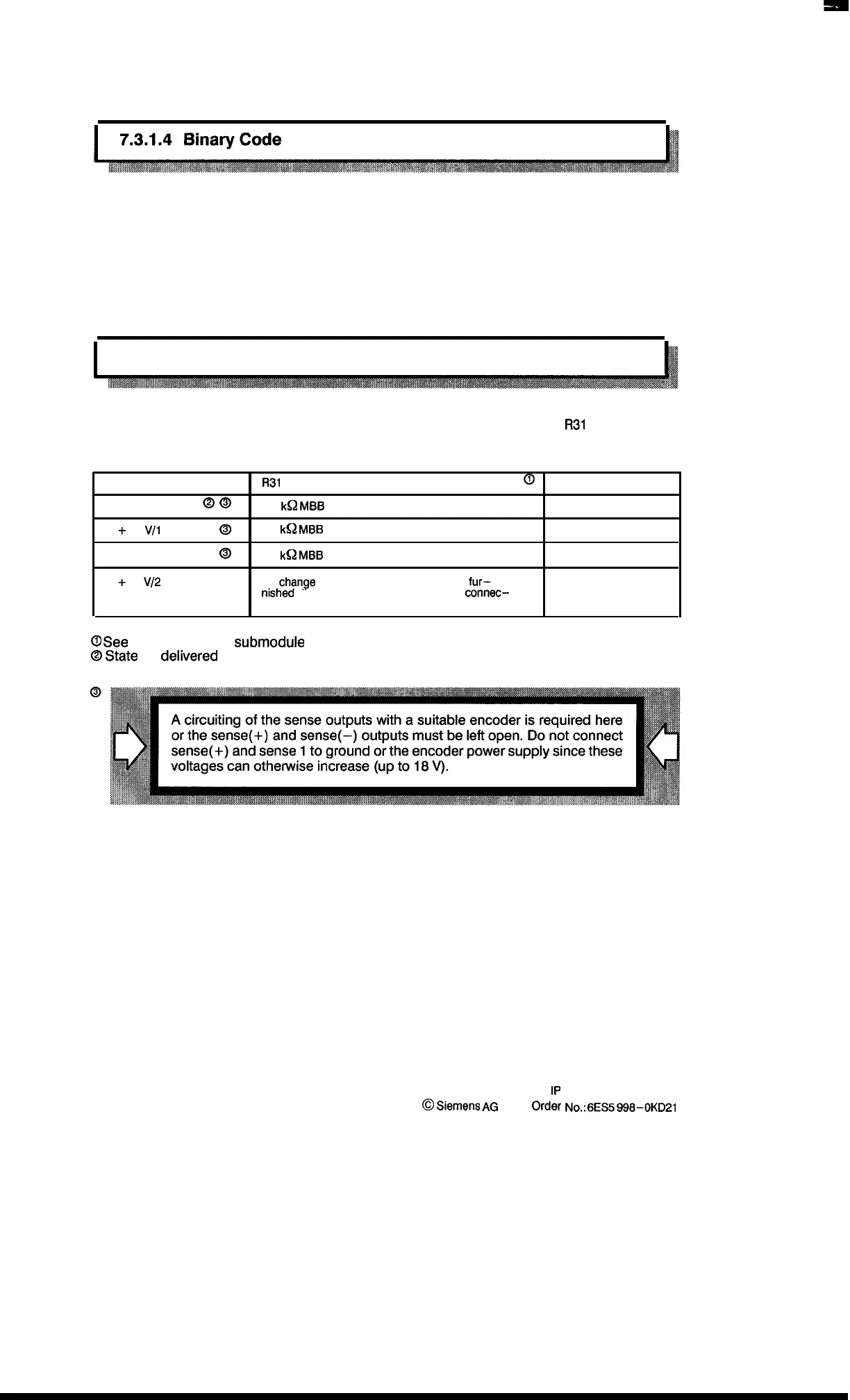
The required encoder supply voltage must be provided by circuitry of resistor
R31
on the absolute
encoder matching module.
Required voltage
R31
Circuitry
@
Pin No.
+5 V/1 A @ @
1.3
I&
MBB
0207
32/48
+ 12 Vll A
@
4.3
k~
MBB
0207
32/48
+ 15 V/l A
0
5.6
k~
MBB
0207
32/48
+ 24
V12
A
No
change
required as the 24 V supply is
fur–
49
nished
directly via a line from the Faston connec–
tor on the basic module.
0
See
layout
of the SS1
submodule
in section 7.3.8.
@
State
as
deiivered
7–8
1P
241 Equipment Manual
@
.Siemens
AG
1989,
Order
No.:
6ES5
gg8-I)KD21
Artisan Technology Group - Quality Instrumentation ... Guaranteed | (888) 88-SOURCE | www.artisantg.com

 Loading...


