Matching Module for Incremental Encoders
R
02/92
—
The area of the external initiating pulse (“a”) must be smaller than one revolution of the encoder.
Otherwise, the zero marking pulse of the encoder would be effective twice.
—
The zero marking pulse of the encoder (pulse width) should only contain one count pulse.
Otherwise, the counter is synchronized as often as the number of pulses contained in the zero
marking pulse.
—
When the external initiating pulse, the zero marking pulse of the encoder, and a count pulse
coincide, the synchronization pulse is generated and the counter is synchronized.
—
In the course of synchronization the counter is loaded with the software-based NV value.
– During synchronization the synchronization bit of the respective channel is set and the related
synchronization LED on the front plate goes off.
I
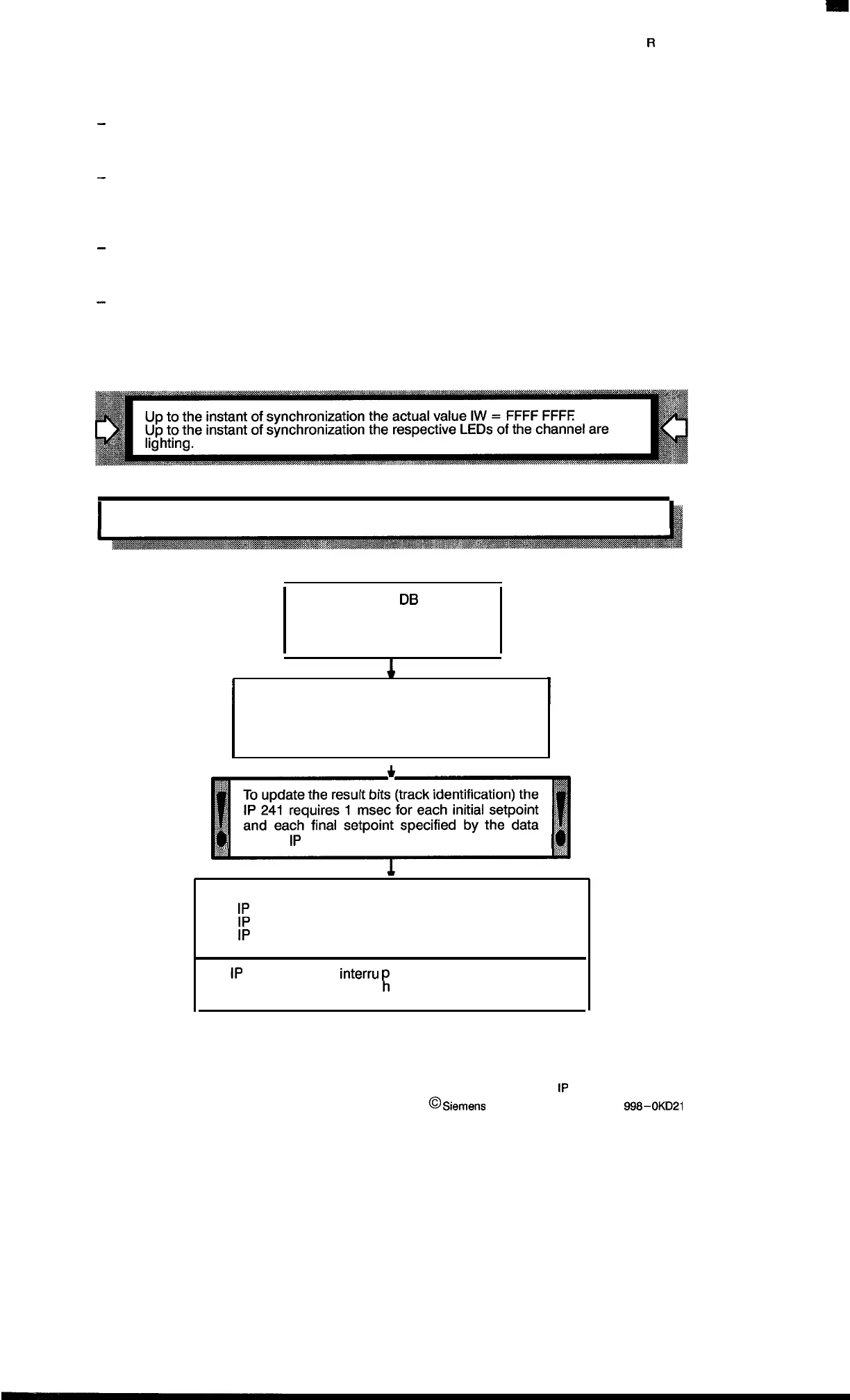
3.3.6
Software Synchronization
Ii
The data block
DB
(IP 241 )
is set with an NV value
(or left at zero).
The software synchronization is called
(e.g., by a standard function block with the
command SS).
1
*
~
block (
1P
241) contents.
The
1P
241 sets the synchronization bit
The
1P
241 dims the synchronization LED
The
1P
241 provides the NV value as the actual value
The
1P
241 causes an
interru
t if the NV value is greater
R
than an entered set value wit interrupt identifier or
always when the NV interrupts are enabled.
3–8
1P
241 Equipment Manual
@
Siemens
AG 1989, Order No.: 6ES5
998-0KD21
Artisan Technology Group - Quality Instrumentation ... Guaranteed | (888) 88-SOURCE | www.artisantg.com

 Loading...


