R 02/92
Matching Module for Incremental Encodera
I
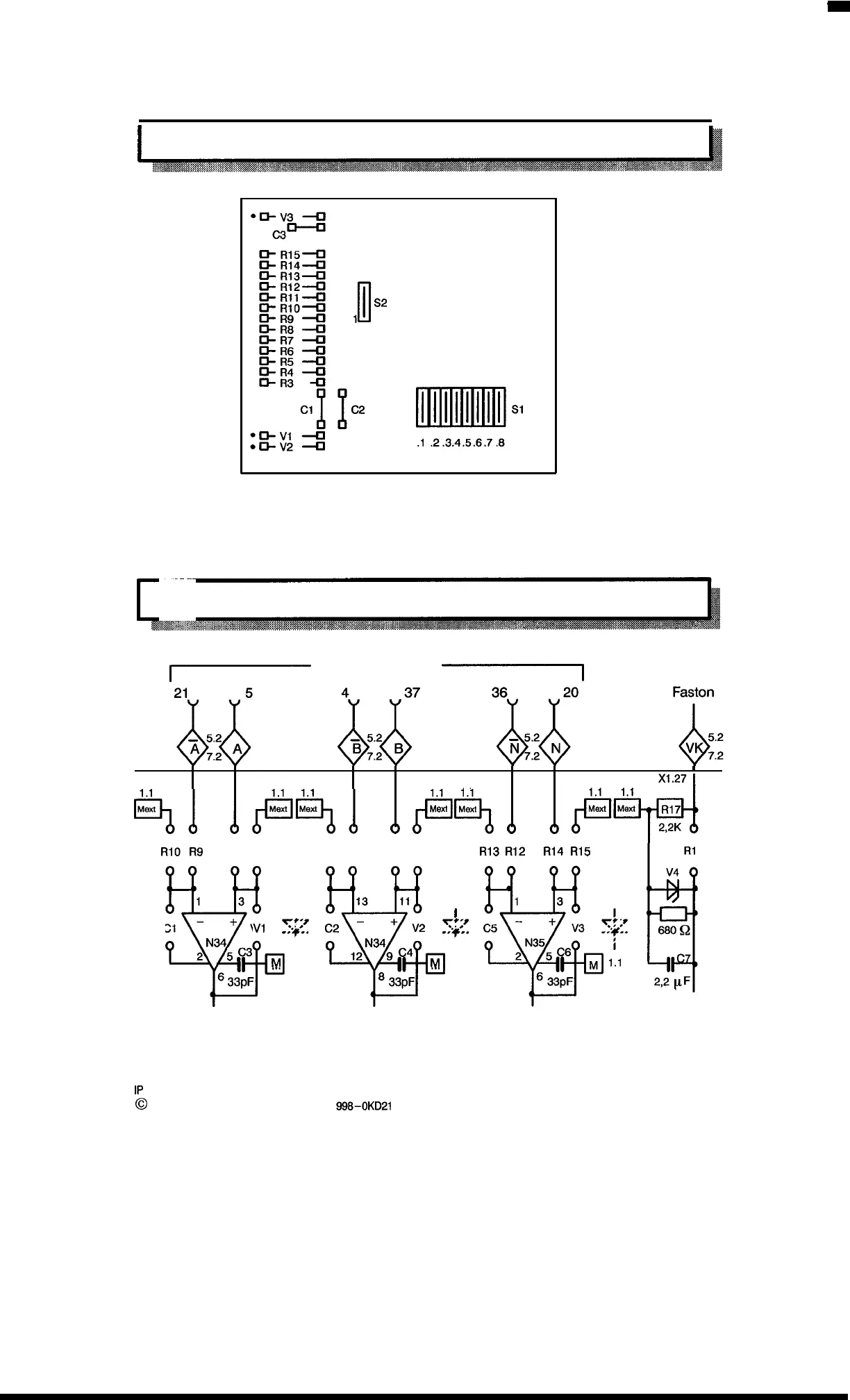
3.3.7
Layout
Ii!
● = Cathode
The layout shows the position of the configurable elements, jumpers, and switches.
3.3.8 Switch Diagram of the Input Amplifiers
~
‘
Ub
‘connector
~
n
X1.34 X1.9 X1.33
X1.8
X1.32 X1.7
%0
OF%.
o
0
0
1.1
P~
Mext
Mexr
X1.271
RIOR9 R7R8
R5R6 R4
R15
R’
R13 R12 R14
%
1
3
I
cl
–
y-;r
+
V1
...+..
N34
i
2
53
M
1.1
6
33PF
%
13 11
I
C2
– +
V2
y?;,
-+-.
N34
i
12
9
C4
M
1.1
8
33pF
@
RI 1
V4
680 Q
2,2 pF
1P
241 Equipment Manual
@
Siemans AG 1989, Order No.: 6ES5
998-0KD21
3–9
Artisan Technology Group - Quality Instrumentation ... Guaranteed | (888) 88-SOURCE | www.artisantg.com

 Loading...


