General Function Description
R 02/92
1.7
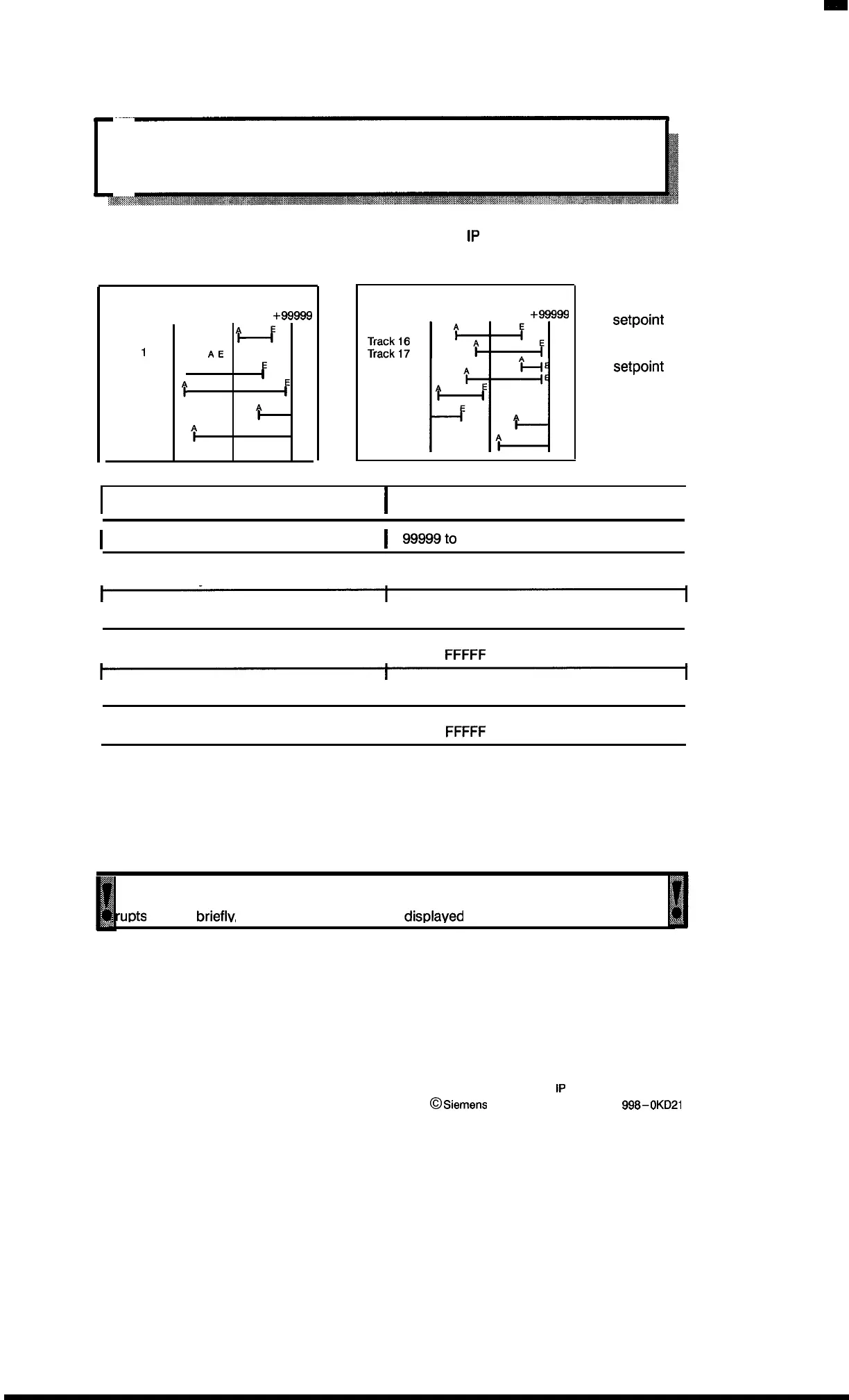
Linear Axis Operating Mode
1.7.1 Function
The linear axis operating mode is the basic setting for the
1P
241 at the initial start-up, after a
power failure, and after software reset.
Channel 1
-99999
0
+99999
Track O
‘H
E
*E
‘A
Track
1
Track 2
A
I
Track 3
[
Track 4
I
t
F
to
I
f
Track 15
Channel 2
–99999
o
+98999
Track 18
I+!
A
“H
Track 19
Track 20
I
‘~E
to
A
I
A
Track 31
A = Initial
setpoint
E = End
setpoint
Encoder
Maximum track area (represented area)
I
I
Incremental encoder
I
- 99999to +99999
I
I
Absolute 1–encoder with
Excess–3 Gray code
I
o to +99999
I
I
Absolute 2–encoder with BCD code
I
o to +99999
I
I
Absolute 2–encoder with binary code
I
o to +99999
or O to
FFFFF
(see section 5.1)
I
I
Absolute 3–encoder analog
I
–
1023 to +1023
I
I
Absolute 4–encoder synchronous–serial
I
o to +99999
or O to
FFFFF
(see section 7.3.1)
I
The operating mode “linear axis” is always used when one or two axes are available per module
where, within the maximum track area, positions are decoded or simple positioning operations
are performed (drives with fixed rotation speed).
On the next pages two typical examples are shown.
II
When the area limits are exceeded with incremental and absolute encoders, then in the
j,
>7
event of linear axes the track identifier bits for all tracks and any parameterized inter-
‘,
;
rurXs
are set
brieflv,
and the next actual value disdaved is zero!
This effect can be avoided as follows:
– Prevent the system from exceeding the limits or
– Use the rotary axis mode (see section 1.8)
1 – 14
1P
241 Equipment Manual
@
Siemens AG 1989, Order No: 6ES5
998-0KD21
Artisan Technology Group - Quality Instrumentation ... Guaranteed | (888) 88-SOURCE | www.artisantg.com

 Loading...


