Matching Module 2
for Absolute Encoders
R 02/92
5.2
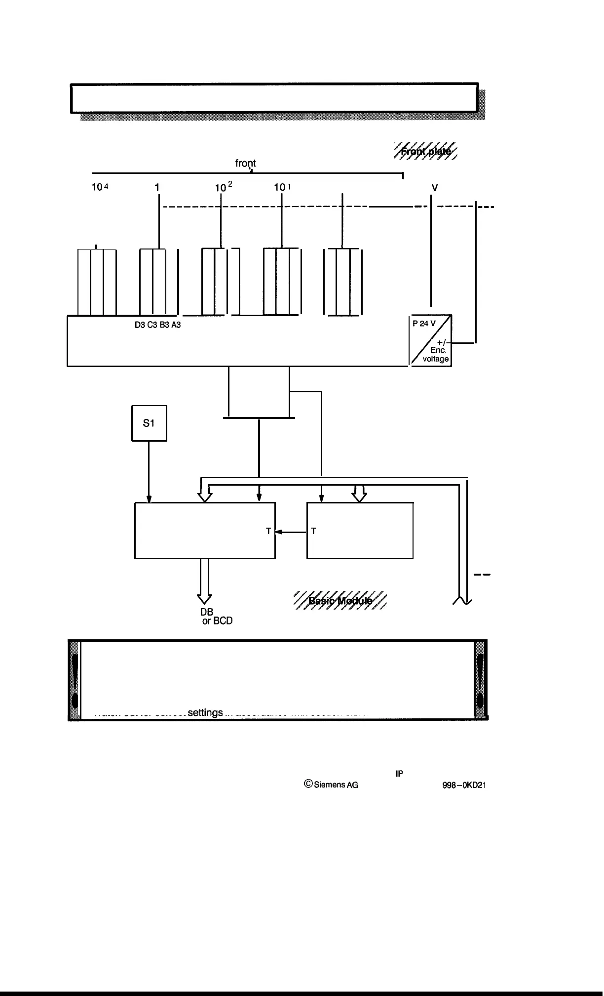
Block Diagram
5–pole
fropt
connector
1
r
I
External Encoder
104
1
)3
,02
101
100
P 24
V
voltage
t
---- --------
‘------r-----t------t--
‘-
-----
---
I
D4C4B4A4
D3C3B3A3
D2C2B2A2
D1 Cl 61 Al
DO CO 60 AO
A
P 24 V
Signal Conditioning
E;;.
D4 . . . to . . . AO
voltage
S1
1
i
1
Addresses
Data
AO
Addresses
output Memory
T
4
T
Control Logic
------------------
-------------------------------
Addresses
Dual
~~BCD
,--
“The actual current value is immediately taken over after power is switched on if
both module and encoder are turned on at the same time. If the encoder is turned on
later, however, the current value can assume undefined states and is not taken over
correctly until the AO position is changed.
if pseudo –tetrades occur, then the encoder signal maybe too slow.
Correction: Match delay with C21.
Watch out for correct settinas in accordance with section 5.3.1.
5–2
1P
241 Equipment Manual
@
.Siemens
AG
1989, Order No.: 6ES5 998-0KD21
Artisan Technology Group - Quality Instrumentation ... Guaranteed | (888) 88-SOURCE | www.artisantg.com

 Loading...


