R 02/92
Matching Module for Incremental Encoders
3.3
Putting into Operation
3.3.1 Setting the Operating Mode
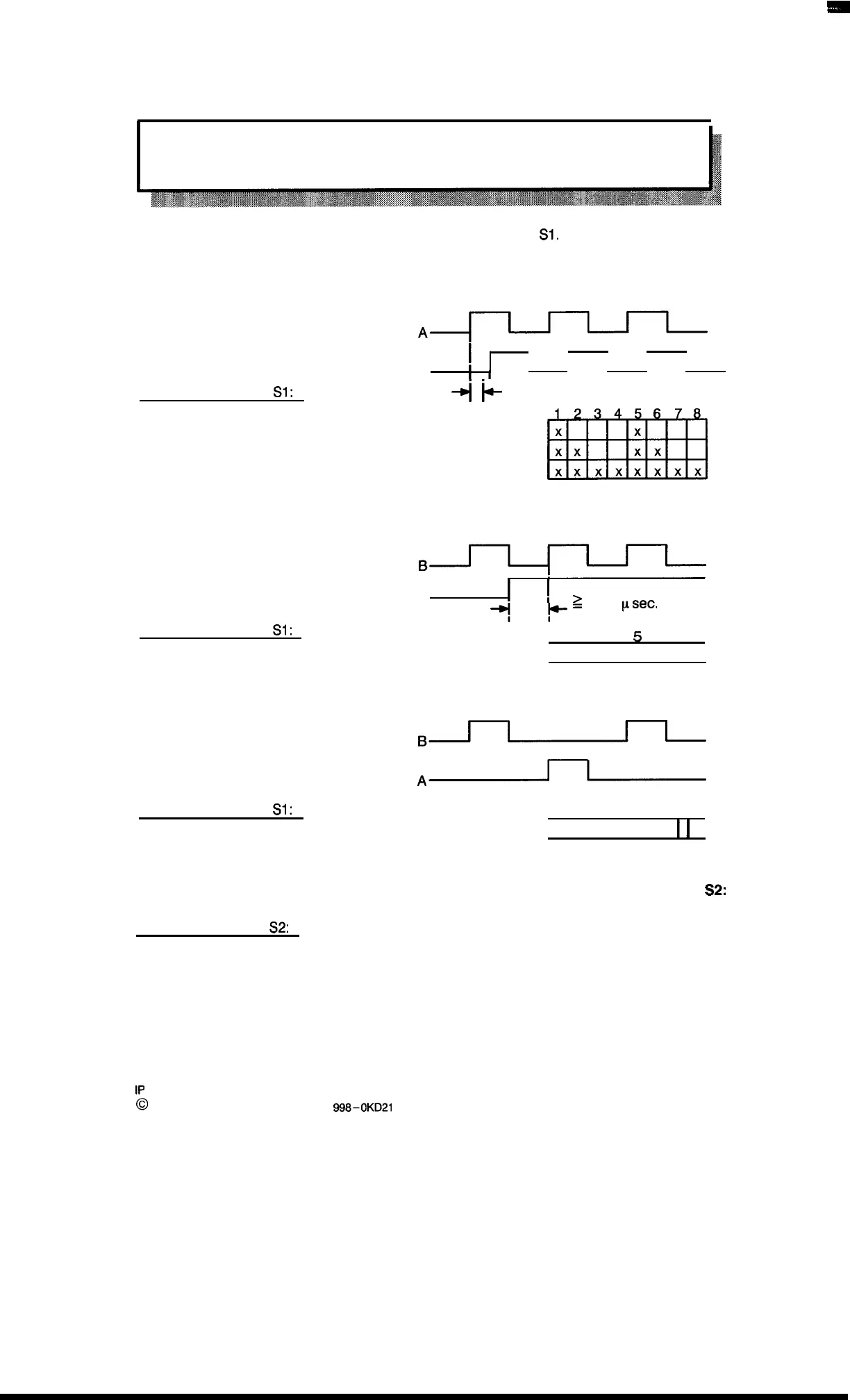
The three possible operating modes are selected with DIP switch
S1.
The settings apply to sym-
metrical and asymmetrical operation.
The encoder provides two pulse trains displaced by 90° in relation to each other:
II
B
I
I
I
I
I
Setting of DIP switch
S1:
4
F
’
00
Closed contacts (x):
One count pulse evaluated
Two count pulses evaluated
Four count pulses evaluated
“
m
The encoder provides neutral pulses (1 pulse train, 1 direction signal):
Pulse
Forward direction
Jl+lJl-
Backward direction
A
~
Z 10
psec,
*,
Setting of DIP switch
S1:
1
2
3
4
5
6
7
8
Closed contacts (x)
x x
The encoder provides direction–sensitive pulses (one pulse per direction):
– Forward pulse
B~
– Backward pulse
A~
Setting of DIP switch
S1:
Closed contacts (x)
6
7
8
1’1
7
1
3
1
4
1
5
1
I
I
I
x x
The specification of the synchronization direction (drive direction) is made by DIP switch
S2:
Setting of DIP switch
S2:
Contact 1 closed:
Synchronize in backward direction
Contact 1 open: Synchronize in forward direction
3–3
1P
241 Equipment Manual
@
Siemens AG 1989, Order No.: 6ES5
998-0KD21
Artisan Technology Group - Quality Instrumentation ... Guaranteed | (888) 88-SOURCE | www.artisantg.com

 Loading...


