Operating Instructions
R
02/92
I
2.4 General Interrupt Routing in the Programmable Controllers
k!
●
●
Setting for the
1P
241 without interrupt processing
DIP Switch S2: All switches OPEN
DIP Switch S1: IRA to
IRD
OPEN
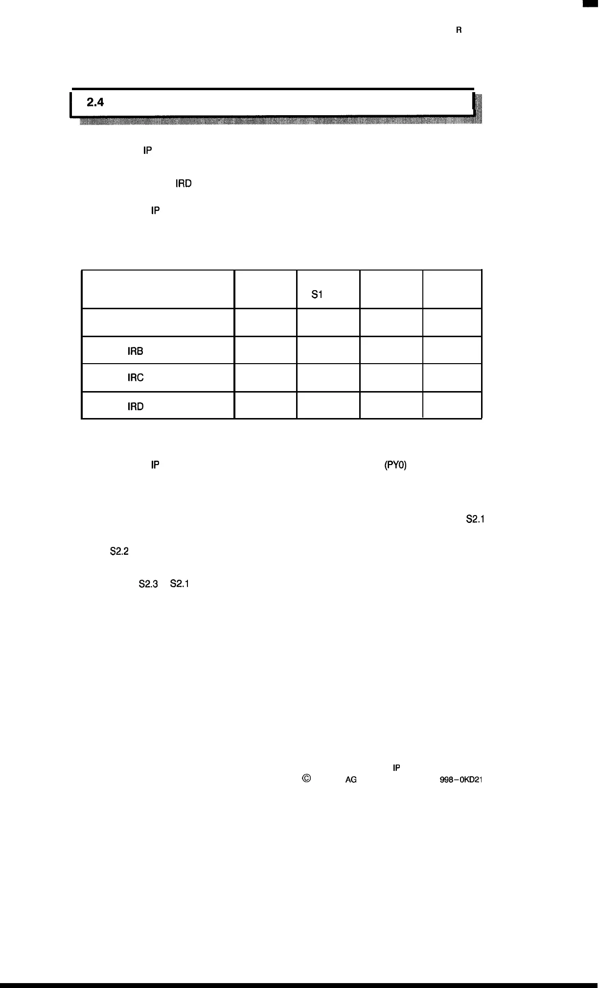
Settings for one
1P
241 with interrupt processing via hardware line
Depending on the interrupt line used, the corresponding switch on the module must be closed.
The switches for the unused lines must be opened.
Switch
Switch Switch
Switch
S1.2
S1
.4
S1 .6
S1 .8
IRA line
x
—
—
—
IRB
line
—
x
—
—
IRC
line
—
—
x
—
IRD
line
— —
—
x
●
x = closed
– = open
Settings for one
1P
241 with interrupt processing via peripheral byte O
(PYO)
and no additional
interrupt module.
The DIP switches for interrupt lines S1 .2/S1 .4/S1 .6/S1.8 must be opened.
The interrupt is output as a group interrupt via the peripheral byte O; in this case switch
S2.1
must be opened.
Switch
S2.2
must be closed. (After recognition of the address O and of the control signal MEMR,
the acknowledgement signal RDY goes to the CPU of the programmable controller.)
The switches
S2.3 to
S2.1
O must be closed.
Thus an evaluation is only possible in OB2 of the programmable controller.
2–6
1P
241 Equipment Manual
@
Siemens
AG
1989, Order No.: 6ES5
998-0KD21
Artisan Technology Group - Quality Instrumentation ... Guaranteed | (888) 88-SOURCE | www.artisantg.com

 Loading...


