R 02/92
Matching Module 1 for Absolute Encoders
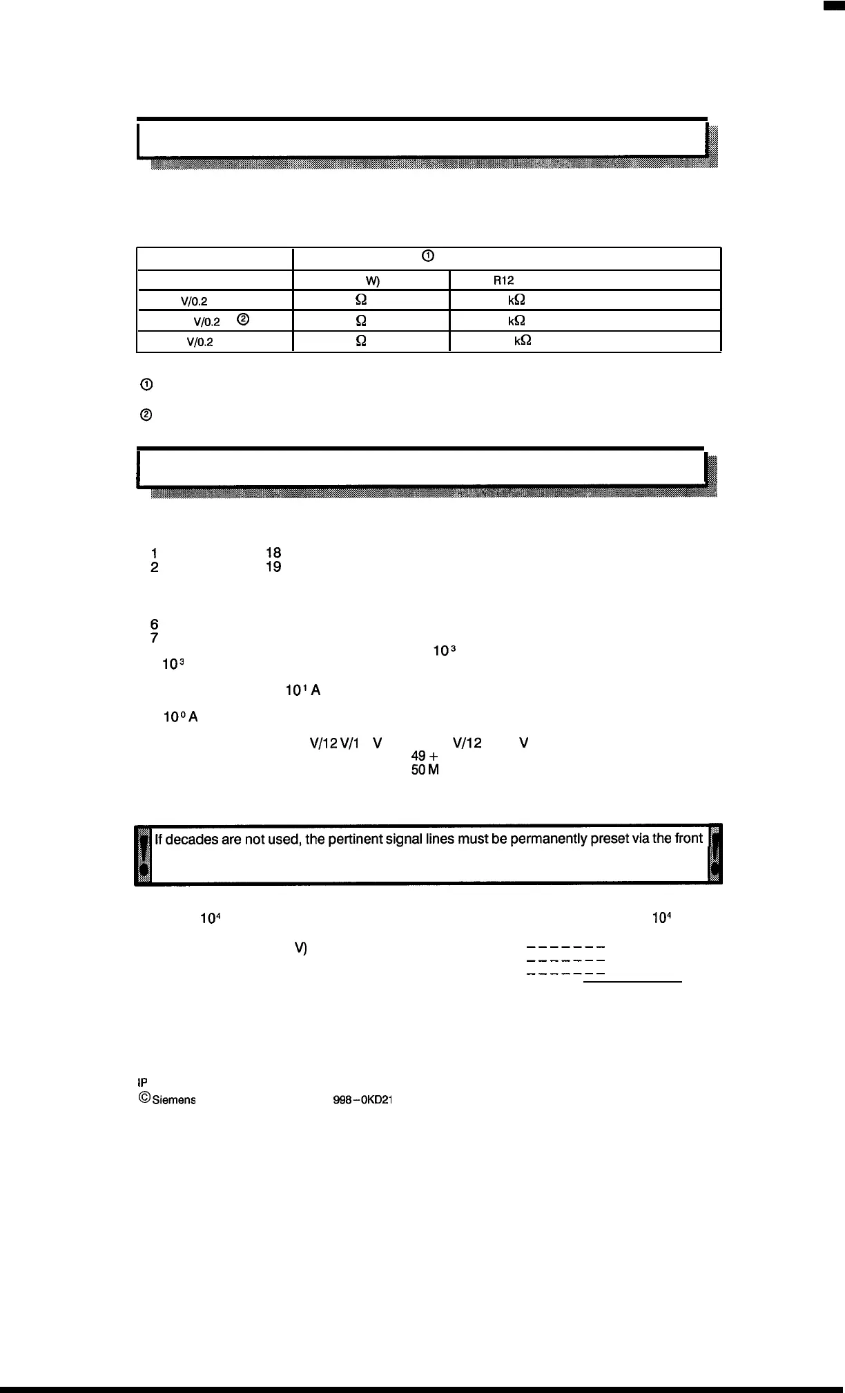
4.3.3 Setting the Encoder Power Supply
The required encoder supply voltage must be provided by suitable adjustment of the circuitry on
the encoder matching module.
Required voltage
Circuitry setting
@
R5 (3
W)
R12
+ 5
V/O.2
A
180
~
33
k~
+ 12
V/O.2
A @
330
Q
91
k~
+ 15
V/O.2
A
330
Q
120
k~
O
See layout of encoder matching module 1 absolute
(Excess–3 gray code)
(see
section 4,3.7).
@
Condition as delivered.
I
4.3.4 Connector Pin Assignment
Ill
Assignment of the sub D connector pins (channel 1 or 2)
34
Change signal
;
;:
35
3
20 36
4
21
37
5
22
38
23104 D
39
?
10
4
c
24 10
4
A
40104 B
8103 D
25103 B
41
103
c
9
10s
A
26102 C 42102 D
10102 B
27 10 I D
43 10
2
A
11 10’ c
28
101A 44 10 I B
12 10° D
29 10° B 45 10’J c
13
10IJA
30
46
14
31
47
15
32 i- 5
VI12
V/l
5
V
48+ 5
VI12
V/75
V
16
33 M
$
~
24 V (Input)
17 M
Pins 32/48 and pins 17/33/50 are parallel and can be used alternatively
connector pins. Jumpers must be soldered in accordance with the gray code:
A connection to the supply voltage means”1”; a connection to M means “O”.
Example:
104
not available (12
V
signal voltage)
Connections
104
:
DCBA
Jumper (12
V)
Pin 48 with pin 40
———————
1
Jumper (M) Pin 33 with pin 23 and 24
———————
0
0
Pin 17 with pin 7
———————
0
Leading “O”
0010
4–5
1P
241 Equipment Manual
@
Siemens AG 1989, Order No.: 6ES5
998-0KD21
Artisan Technology Group - Quality Instrumentation ... Guaranteed | (888) 88-SOURCE | www.artisantg.com

 Loading...


